Disassembly/Assembly
56
Keypad and
Keypad Option
Board
Reassembly
1. Insert the keypad into the front cover. Align the keypad to the pins in the front
cover.
2. Replace the board on the locator pins.
3. Replace the keypad retainer legs on the PTT side first. Then, press the
retainer down and snap the other two legs into place on the universal
connector side; make sure that all four legs snap into place. If necessary, use
a small, flat-bladed screwdriver to put pressure on the corner bend of each
retainer leg.
Display
Reassembly
1. Slide the two bottom tabs of the display module, with the LCD facing the front
housing lens, into the grooves located above the keypad assembly area in the
front cover housing. Gently press on the upper portion of the display until it
snaps into place past the two small hooks in the housing.
2. Connect the display flex to the keypad option board connector.
Speaker,
Microphone, and
Universal
Connector Flex
Reassembly
1. Insert the microphone boot into the pocket in the front cover housing.
2. Insert the microphone boot plastic retainer. Make sure the retainer is securely
hooked to the front cover.
3. Center the speaker in the speaker recess. Make certain the speaker is
correctly nested inside the front cover.
4. Before you replace the speaker retainer, be sure the retainer is placed
between the speaker-microphone flex circuit and the speaker. Insert the flat
end of the speaker retainer into the opening in the front cover. Press the other
end of the retainer against the speaker. Hold the retainer in place with your
thumb while pushing down on the retainer with a flat-bladed screwdriver. Use
the screwdriver to push down on the portion of the speaker retainer that is
pointing toward the bottom of the radio. Move the retainer by pushing it toward
the bottom of the radio. Slide it into the front cover slot above the display.
5. Connect the universal flex to the pins and press into place.
IMPORTANT NOTE: Always replace the two conductive pads (P/N:
2671104L01 and 2616342H02 - EMI sheild, electrically
conductive gasket) after rework.
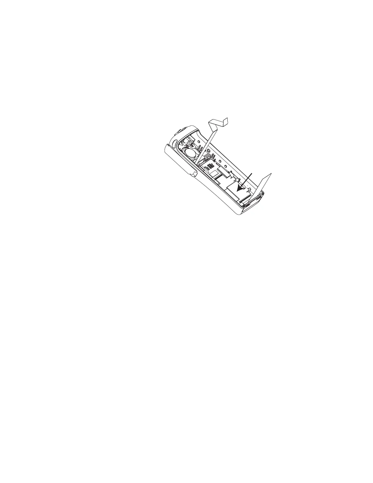
Figure 38. Lock Retainer Catches to Radio Body

 Loading...


