Basic Theory of Operation
7
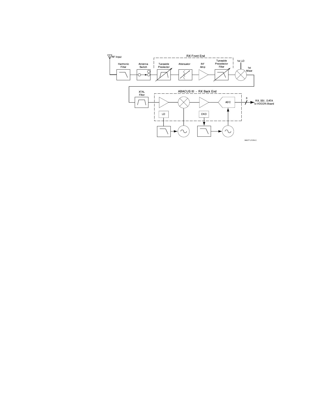
and mixed with the first local-oscillator signal generated by the voltage-controlled
oscillator (VCO).
The resulting intermediate frequency (IF) signal is fed to the IF circuitry, where it is
again filtered and amplified. This amplified signal passes to the digital back-end IC,
where it is mixed with the second local oscillator to create the second IF ( 2.25 MHz
for VHF). It is then converted to a digital bit stream and mixed a third time to
produce a baseband signal. This signal is passed to the VOCON circuitry through
a current-driven differential output.
In the VOCON circuitry, the digital-signal processor (DSP) support IC digitally filters
and discriminates the signal, and passes it to the DSP. The DSP decodes the
information in the signal and identifies the appropriate destination for it. For a voice
signal, the DSP routes the digital voice data to the CODEC for conversion to an
analog signal. The CODEC then presents the signal to the audio power amplifier,
which drives the speaker. For signalling information, the DSP decodes the
message and pass it to the microcontrol unit.
Transmitting When the radio is transmitting (see Figure 3), microphone audio is passed through
gain stages to the CODEC where the signal is digitized. The CODEC passes digital
data to the DSP where pre-emphasis and low-pass (splatter) filtering are done. The
DSP passes this signal to a digital-to-analog (D/A) converter where it is
reconverted into an analog signal and scaled for application to the voltage-
controlled oscillator as a modulation signal.
Figure 2. Receiver Block Diagram
RF Input
RX Front End
Harmonic
Filter
ADC
LO
CKO
RX_SSI_ DATA
to VOCON Board
XTAL
Filter
ABACUS III - RX Back End
Antenna
Switch
Tuneable
Preslector
RF
Amp
Attenuator
Tuneable
Preselector
Filter
1st
Mixer
1st LO
3
MAEPF-27278-O

 Loading...


