Disassembly/Assembly
49
9. Lay the chassis down. Rotate the front cover backward and slightly away from
the chassis.
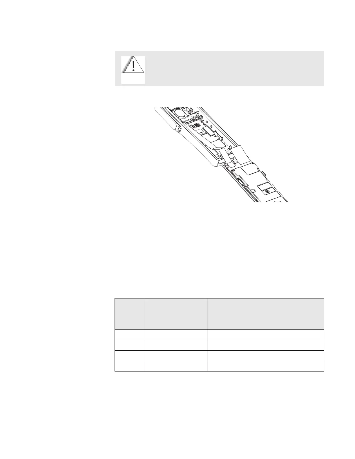
10. Carefully lift the latches on the main circuit board to release the flexible
circuits from their connectors.
NOTE: For proper reassembly, note how the flex circuits are folded.
11. Remove the concentric lever from the front cover assembly.
Chassis
Disassembly
For this section, please refer to the Model III exploded view and parts list on
page 39 for part numbers and more information on the location of parts in the radio.
1. If disassembly of the chassis or the main board is required, then use a
TORX™ screwdriver with a T7-IP head to remove the five screws holding the
main board and shield to the chassis.
Flexible ribbon circuits (flexes) connecting the front cover
assembly and the chassis prevent you from completely
separating the two units. Display radios and radios with option
boards have two flexes.
Figure 31. Unlatching the Flex Connectors
C a u t i o n
Table 18. Chassis Disassembly
Exploded
View
Item
Number
Motorola Part Number Description
1 1578458A04 Cover Assy, Front Model III
2 7516330H01 Keypad, Full
4 4216345H01 Retainer
8 7285726C04 Display, Flat Panel, LCD Module

 Loading...


