Disassembly/Assembly
58
3. Push down the latches on the connectors to hold the flex circuits to the main
board.
NOTE: Be sure the concentric lever is not in place on the frequency knob
shaft when reassembling the chassis with the front cover assembly.
4. Align the volume knob shaft and the frequency switch shaft with their
respective holes in the front cover. Slowly reassemble the chassis and front
cover assemblies. Slowly slide the volume knob and frequency switch shafts
into their respective holes in the front cover.
NOTE: Make sure the flex circuits are correctly folded in place. Take special
care to prevent pinching or excess binding of these flexes.
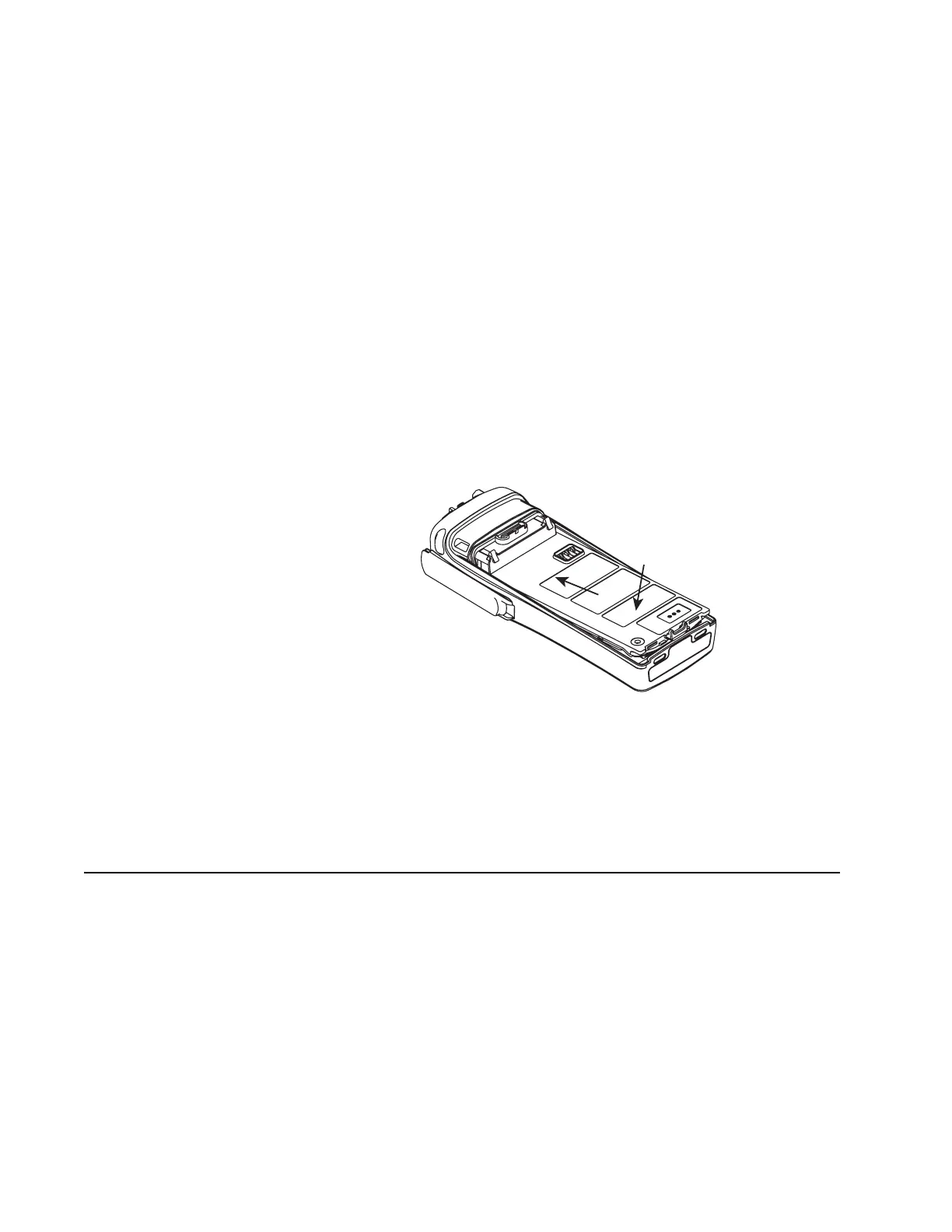
5. Push the chassis assembly completely into the top of the front cover until it
settles in place.
NOTE: Be sure the O-ring is properly seated.
6. Press down at the bottom of the chassis until the chassis snaps into place in
the front cover.
7. Reassemble the concentric lever to the frequency knob shaft by aligning the
protrusions in the lever with the openings in the shaft. The triangular-shaped
side of the lever should point toward the back of the radio.
8. Reassemble the Teflon washer to the volume knob shaft. Reassemble the
knobs, dust cover, antenna, and battery.
Ensuring Radio
Immersibility
This section discusses radio immersibility concerns, tests, and disassembly and
reassembly of ASTRO XTS 2500I radios.
Standards ASTRO XTS2500I radio models meet the stringent requirements of U.S.
MIL-STD-810C, Method 512.1, Procedure I, MIL-STD-810D, Method 512.2,
Procedure I, MIL-STD-512.3, Procedure I, and MIL-STD-512.4, Procedure I, which
require the radio to maintain watertight integrity when immersed in three feet of
water for two hours.
Figure 40. Fastening the Chassis

 Loading...


