1
Introduction
1
General This manual covers information needed for level one and two troubleshooting.
Level one troubleshooting consists of radio programming, tuning (via CPS/tuner),
knobs replacement, and installation and removal of antenna, belt clip, battery, and
universal connector cover. Level two troubleshooting consists of everything listed
in level one, plus the identification and replacement of Field Replaceable Units
(FRUs). No soldering will be allowed; only board swapping.
Included in this manual are radio specifications for the VHF frequency band; a
general description of ASTRO Digital XTS 2500, XTS 2250, and XTS 1500 models,
and analog MT 1500 and PR 1500 models; recommended test equipment; service
aids; radio alignment procedures; general maintenance recommendations; and
procedures for basic assembly and disassembly.
NOTE: Hereinafter, the series of radios including the ASTRO
Digital XTS 2500, XTS 2500I, XTS 2250, and XTS 1500,
and analog MT 1500 and PR 1500, is referred to as the
“XTS 2500/2250/1500 radios”.
Notations Used
in This Manual
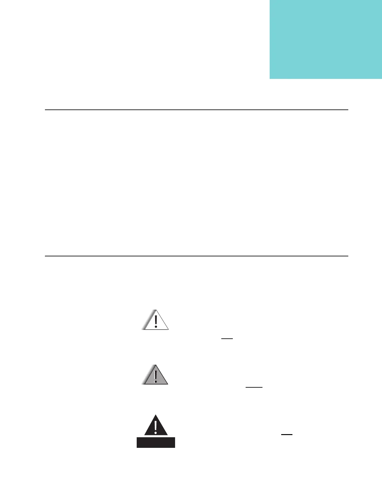
Throughout the text in this publication, you will notice the use of warning, caution,
and note notations. These notations are used to emphasize that safety hazards
exist, and care must be taken and observed.
NOTE: An operational procedure, practice, or condition, etc.,
which is essential to emphasize.
CAUTION indicates a potentially hazardous situation which,
if not avoided, may
result in equipment damage.
C a u t i o n
WARNING indicates a potentially hazardous situation
which, if not avoided, could
result in death or injury.
W A R N I N G
DANGER indicates an imminently hazardous
situation which, if not avoided, will
result in death o
injury.
D A N G E R

 Loading...


