Disassembly/Assembly
54
Speaker,
Microphone, and
Universal
Connector Flex
Disassembly
For this section, please refer to the Model III exploded view and parts list on page
39 for part numbers and more information on the location of parts in the radio.
1. The speaker-microphone assembly can be removed without the disassembly
of the display or the keypad assemblies. If disassembly of the speaker-
microphone assembly is necessary, removal of the universal connector dust
cover is optional (see Figure 23 on page 44).
2. Remove the plastic spacer at the bottom of the speaker. The spacer can be
removed by pulling upward with a slight, side-to-side motion until it clears the
retaining ribs in the front cover. Take special care to prevent damage to the
tail of the speaker flex circuit while the flex is still in place.
3. Using a screwdriver, push down on the portion of the speaker retainer bracket
that is pointing toward the bottom of the radio. Then, remove the retainer by
slightly pushing it toward the top of the radio until you slide it past the front
cover slot.
4. Remove the microphone boot retainer by inserting a penknife-sized
screwdriver in the notch between the retainer and the housing. Pry the
retainer away from the housing and remove the clip.
5. Remove the microphone rubber boot by sliding it out of the pocket in the front
cover. Take care not to pull on the flex cable while pulling on the microphone
boot. Unless you are replacing the microphone, leave it in the boot. At this
point, the speaker and microphone are disconnected, but the assembly is still
attached to the universal connector by 13 pins in the printed circuit backer
board.
6. To remove the speaker-microphone flex circuit from the universal connector,
carefully grasp the flex circuit at a point directly across from the universal
connector pins. Applying firm pressure, gradually pull the flex away from the
pins.
NOTE: There are notches on the ends of the 13-pin printed circuit backer
board. If necessary, you can insert a small screwdriver in one of the
notches to pry the backer board away from the front cover.
After the universal connector portion of the speaker-microphone flex circuit is
detached, the assembly can be completely removed. If it is necessary to replace
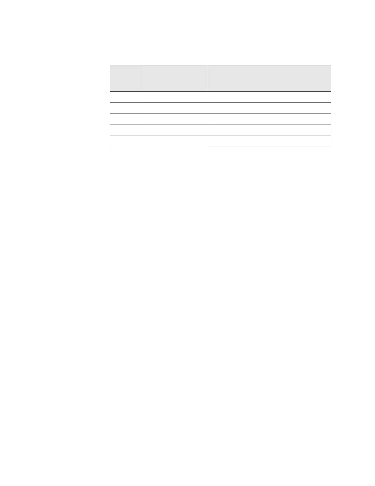
Table 22. Speaker, Microphone, and Universal connector Flex Disassembly
Exploded
View Item
Number
Motorola Part Number Description
1 1578458A04 Cover, Assy, Front Model III
29 4385717D01 Spacer, Plastic
30 4271058L01 Retainer, Speaker
32 8416579H01 Board, Circuit, Flex Speaker Mic
33 1485218D01 Boot, Microphone

 Loading...


