8-1
CHAPTER 8
CPU RAM Backup Battery
N
N
o
o
t
t
e
e
:
:
The following pertains only to the Power Supply Module – Less.
This backup battery option is used when replacing the main power DC source and / or
replacing I/O Modules inside the multi-slot I/O card cage.
It is not recommended to insert an I/O Module into the multi-slot I/O card cage of the
IRRInet-XL RTU while the RTU is powered on. To replace an I/O Module first power off
the RTU then remove or insert the new I/O Module. However, powering off the RTU
causes all the data inside the CPU Module RAM to be erased. In order to preserve the
data inside the CPU Module RAM while the RTU is
powered off perform the following steps:
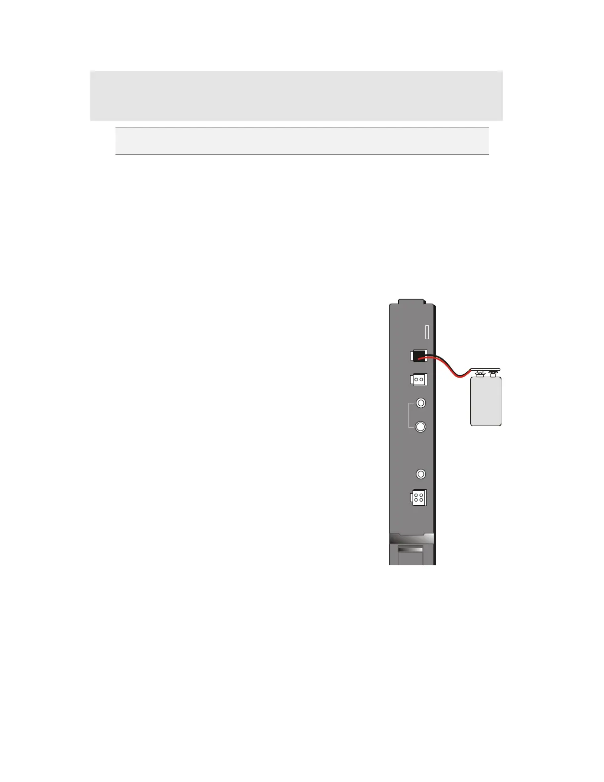
Assembly Instructions (See Figure 8-1):
1. While the IRRInet-XL RTU is powered on connect
a small 9 VDC battery to the Power Supply
Module “BAT” connector. Refer to Figure 8-1 CPU
RAM Backup Battery – User Connections.
2. Power off the RTU.
3. Replace the I/O Module.
4. Power on the RTU.
5. Remove the 9 VDC backup battery from the
Power Supply Module.
6. All data in the CPU Module RAM has been saved
and is available upon the new RTU power up.
Figure 8-1 CPU RAM Backup Battery – User
Connections
POWER
SUPPLY
BAT
AUX
DC
ON
OFF
PWR
PWR
IN
9V
Batter
Power Supply Module –
Less (FPN5957)
FKN8035
 Loading...