2-25
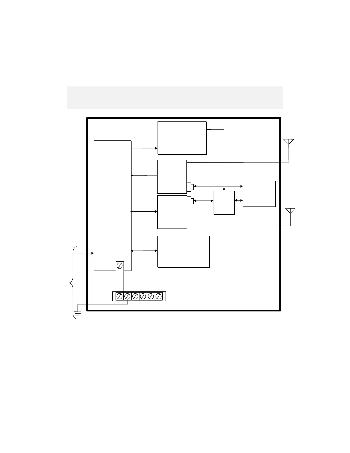
2.8.4 Connecting the RTU by Two Separate Mobile Radios
The following diagram (See Figure 2-22) illustrates the proper connections for
connecting both the CPU Port 2 (Intrac protocol) and Port 3 (MDLC protocol) to
separate Mobile Radios using the 8 Ampere Power Supply.
N
N
o
o
t
t
e
e
:
:
Port 2 (Intrac) is to be connected to the “Low Power” Radio and Port
3 (MDLC) is to be connected to the “High Power” Radio.
VCC
CMU
VCC
CMU
3-Slot Chassis
AC
Input
ntenna
Power
Supply
LOGIC
RADIO
PGND
IN
BATT
Back Up Batter
Radio
(
High Power)
Radio
(
Low Power
)
Jumper Strip
CPU
Module
Port 3
Port 2
Data
Data
Protective Gnd Strip
Power Supply
Module
(Less)
AUX
BA
PWR
IN
Primary
Power Supply
Radi
Powe
Suppl
u
Powe
Supply
AUX
Batter
Powe
Suppl
Comm
Cabl
dapto
Antenna
Comm
Cable
dapto
8 Ampere
Figure 2-22 Connecting the RTU by two Separate Mobile Radios - Interconnection
Diagram
 Loading...