4-4
Port 2 Wire Line
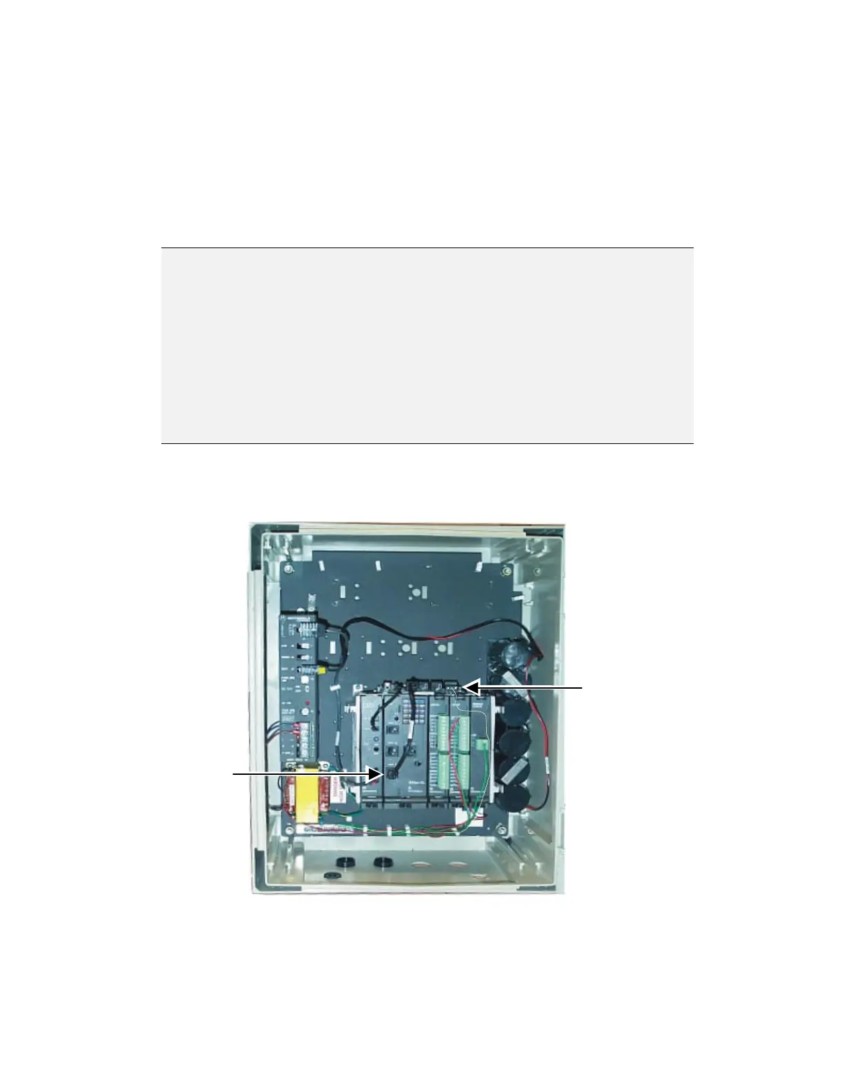
1. Connect the CMU power connector to the Power Supply Module “AUX”
connector using the power cable (p/n: FKN4869). When powered on, the CMU
LED should light.
2. To enable only Wire Line communication through Port 2, short pins 2 and 3 of
jumper P3 (Channel Monitor) on the CMU board (See Figure 4-1). Note that
this is not the factory default.
N
N
o
o
t
t
e
e
:
:
Port 2 should be set to “High” in the Site Configuration | Channel
Monitor option (This is the factory default).
When Port 2 is used for Wire Line communication, the IRRInet-XL
RTU is usually set as “Master” (“Master” is the factory default
position). For “Master” operation, the Jumper (P2) pins 1 and 2 are
shorted together (See Figure 4-1).
To change the IRRInet-XL RTU to “Slave” Mode change the position
of the P2 jumper so that pins 2 and 3 are shorted together.
3. To enable Port 2 Intrac using both a radio and a wire line connection – refer to
Table 4-1 for P3 Jumper and Site Configuration Settings.
CPU Port2
Connects to
CMU Port2
CMU Line
connects to
another UUT
CMU Line
Figure 4-4 CMU Module – Port 2 Wire Line User Connections
 Loading...