3-2
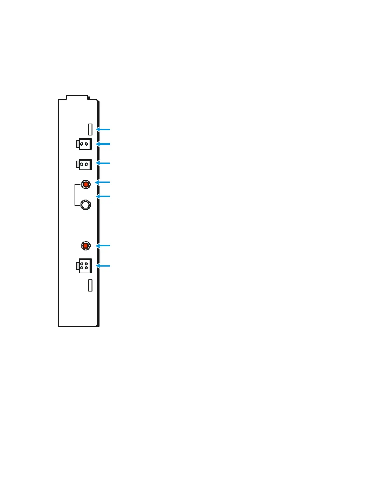
3.1.3 Front Panel - Controls, Indicators and Connectors
The front panel controls, indicators and connectors of the Power Supply Module are
described in Figure 3-1:
POWER
SUPPLY
BAT
AUX
DC
ON
OFF
PWR
PWR
IN
BAT - Connector. Used for interconnecting 12 VDC
power between the Power Supply module and the battery
Replaceable fuses located inside panel
AUX - D C outpu t c onnec tor.
Supplies 12 V DC power to Portable Radio
DC ON/OFF - S w itc h. Co ntrols the DC
output of the Power Supply module
Indication LED. Lit when the Power Supply receives valid input Voltage
P ow er In Connec tor
FKN4463 cable - T o
45 VA Power Transformer
FKN4469 cable
-
12
-
16 V DC
Indication LED – Lit
when Power Supply Module outputs DC Voltage
Figure 3-1 Power Supply Module – Front Panel
 Loading...