3-13
3.4.2 Diagnostic LED Panel
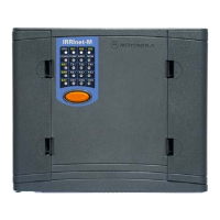
Use the matrix display on the CPU Module for diagnostics and testing of the I/O-AC
Module. The top row indicates which module (CPU, M1, M2 or M3) the LED panel is set to
display and the blue numerals on the LED panel are the I/O indications.
Press the pushbutton (P.B.) once momentarily to activate the LED panel. Then, press the
pushbutton until the I/O-AC slot LED is on. The LEDs will light in the following order: CPU,
M1 (I/O Module 1), M2 (I/O Module 2), and M3 (I/O Module 3). Verify that the relevant
LED is lit.
For example; Figure 3-7 shows indications from the module in slot number 1 (M1). LED
number 1 is on, indicating that the module is reading signal from Input number 1 (DI - 1).
LED number 11 is on, indicating that the module is energizing Output number 9 (OUT - 9)
Table 3-4 specifies the LED indications for the I/O-AC Module.
CPU M1 M2 M3
LOAD
1
CONF
5
APPL
9
MON
13
RST
2
Tx1
6
Tx2
10
Tx3
14
ERR
3
Rx1
7
Rx2
11
Rx3
15
BAT
4
CM1
8
CM2
12
CM3
16
Figure 3-7 I/O-AC Module LED Display
Table 3-4 I/O-AC Module Indication Display
LED # I/O Indication LED # I/O Indication
1 DI – 1 9 OUT – 7
2 DI – 2 10 OUT – 8
3 OUT – 1 11 OUT – 9
4 OUT – 2 12 OUT – 10
5 OUT – 3 13 OUT – 11
6 OUT – 4 14 OUT – 12
7 OUT – 5 15 OUT – 13
8 OUT – 6 16 OUT – 14
I/O LEDs (1 to 16)
P.B.
 Loading...