5-5
5.3 RTU-to-RTU Connections
5.3.1 RTU-to-Multiple RTUs Time Synchronization Using SYNCH
Broadcast (via Port 1B)
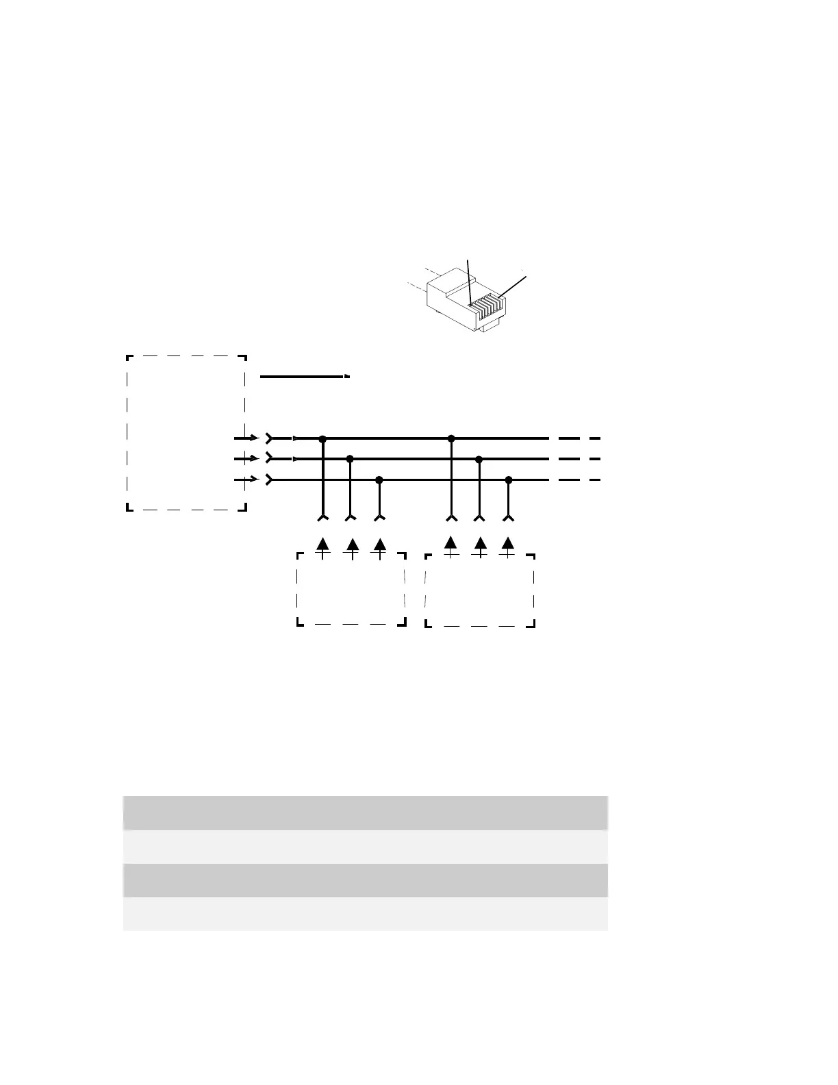
The interconnection diagram below describes the Time Synchronization method, which
uses a SYNCH broadcast via port 1B (See Figure 5-4).
SITE A
(SYNCHRONIZING
SITE)
TxDATA
TxCLK
GND
1
6
4
PORT
1B
BROADCASTING
TRANSMISSION ONLY
2 3
4
Rx
DATA
Rx
CLK
GND
SITE B
2 3
4
Rx
DATA
Rx
CLK
GND
SITE C
PORT
1B
PORT
1B
RJ45
Connector
Pin No. 1
Pin No. 8
Figure 5-4 Time Synchronization using SYNCH Broadcast – Interconnection
Diagram
5.3.2 RTU-to-RTU Asynchronous Communications Connection
This section provides data on the cable recommended for the RTU- to-RTU RS-232
asynchronous interconnection (not supplied) (See Figure 5-5). The following table
defines the RTU port for this connection type.
CPU Port No. Piggyback Board Toolbox Definition
1B – RS-232 UART RTU-to-RTU (MDLC)
2 – RS-232 UART RTU-to-RTU (MDLC)
3 FRN5724A RS-232 UART RTU-to-RTU (MDLC)
 Loading...