2-10
Controls, Indicators, And Connectors For 8 Ampere Power Supply
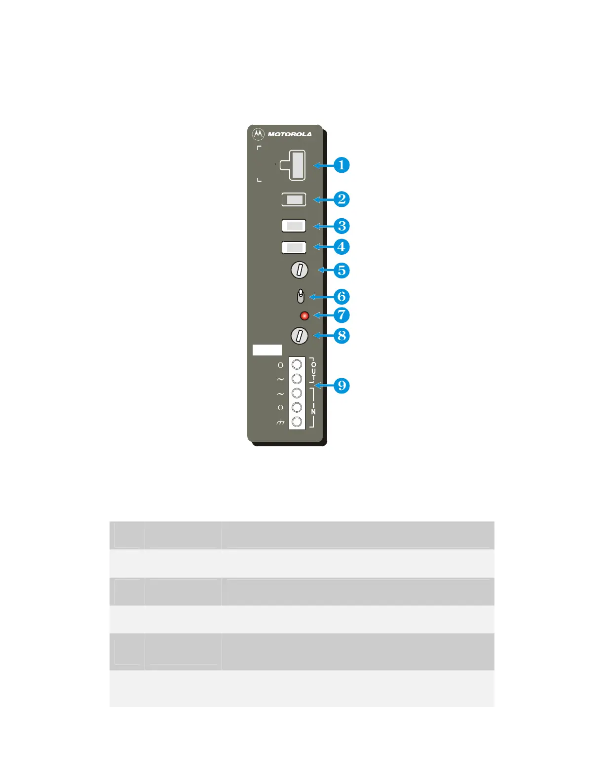
The power supply controls, indicators, and connectors are described in Table 2-1 and
illustrated in Figure 2-11.
N
L
L
N
P GND
230 V 50Hz 1A
230V
FUSE (SB)
250V 3A T
FUSE (SB)
10A
AC ON
OFF
ON
DC OUT
J1
BATT
RADIO
AUX
J3
L
O
G
I
C
+
+
+
F2
+
G
G
FPN5225A
P OX
P F
D D
L B
J2
230V
F1
Figure 2-11 8 Ampere Power Supply Front Panel
Table 2-1 8 Ampere Power Supply – Front Panel Controls, Indicators, and
Connectors
Item Name Function
1 LOGIC (J4) Connects DC power to Power Supply Module
2 AUX (J3) Supplies 12 VDC power to “Low Power” Mobile Radio
3 RADIO (J2) Supplies 12 VDC power to “High Power” Mobile Radio
4 BATT (J1)
Interconnects 12 VDC power from the backup battery
to the power supply
5 F2
Fuse (10 Amp) to protect against DC power overload
to battery
 Loading...