OPERATING AND MAINTENANCE MANUAL
Chapter 7 - Electronic controller
TAEevo Tech 015÷802 60 Hz UL
75
The data in this manual are not binding and they can be modified by the manufacturer without notice. Reproduction of this manual is strictly prohibited
EN
ENGLISH
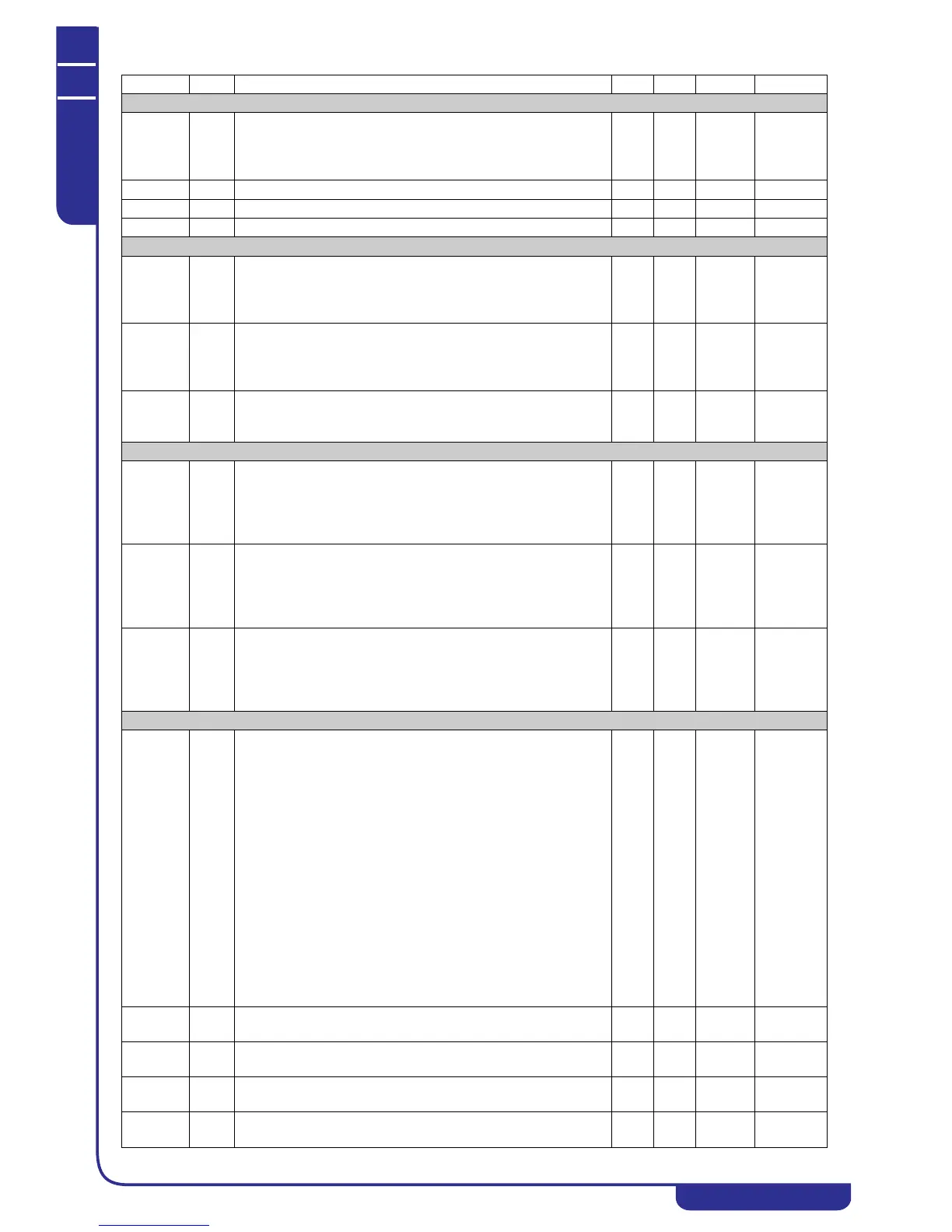
Display presentation in STD-BY
dP10 S Ichill display presentation in STD-BY:
0= Shows label “STD-BY”
1= Shows parameters defined by par. dP1 and dP2
2= Shows label “OFF”
02
Pr1 U User password 0 999
Pr2 S Service password 0 999
Pr3 C Manufacturer password 0 999
Unit
CF01 C Defines the type of unit to control:
0= Air / air chiller
1= Air / water chiller
2= Water / water chiller
02
CF02 C Unit operation selection:
1= Chiller only
2= Heat pump only
3= Chiller with heat pump
13
CF03 C Condensing units:
0= No
1= Yes
01
Compressors
CF04 C Number of compressors present in circuit no. 1:
1= 1 compressor
2= 2 compressors
3= 3 compressors
4= 4 compressors
14
CF05 C Number of compressors present in circuit no. 2:
0= None
1= 1 compressor
2= 2 compressors
3= 3 compressors
03
CF06 C Number of capacity steps per compressor:
0= None
1= 1 step
2= 2 steps
3= 3 steps
03
Analogue inputs
CF07 C Operation in temperature or pressure from analogue input:
0= Operation in temperature / pressure NTC - 4...20 mA:
The condensing temperature is controlled via an NTC probe while
a transducer with 4..20mA output must be used for the
evaporation pressure control of circuits 1 and 2 and the pressure
probe configured as auxiliary output 1 and 2.
1= Operation in pressure with 4...20 mA input:
A transducer with 4..20mA output must be used to control the
condensing or evaporation pressures
2= Operation in temperature / pressure NTC - 0...5V:
The condensing temperature is controlled via an NTC probe while
a ratiometric transducer with 0..5V input must be used for the
evaporation pressure control of circuits 1 and 2 and the pressure
probe configured as auxiliary output 1 and 2.
3= Operation in pressure with 0...5V input:
A ratiometric transducer with 0..5V input must be used to control
the condensing or evaporation pressures.
03
CF08 C PB1 configuration
If configured as a digital input.
0
o 1
28
c75
CF09 C PB2 configuration
If configured as a digital input.
0
o 1
28
c75
CF10 C PB3 configuration
If configured as a digital input.
0
o 1
35
c75
CF11 C PB4 configuration
If configured as a digital input.
0
o 1
35
c75
Parameter Level Description Min. Max. UM Resolution