OPERATING AND MAINTENANCE MANUAL
Chapter 7 - Electronic controller
TAEevo Tech 015÷802 60 Hz UL
83
The data in this manual are not binding and they can be modified by the manufacturer without notice. Reproduction of this manual is strictly prohibited
EN
ENGLISH
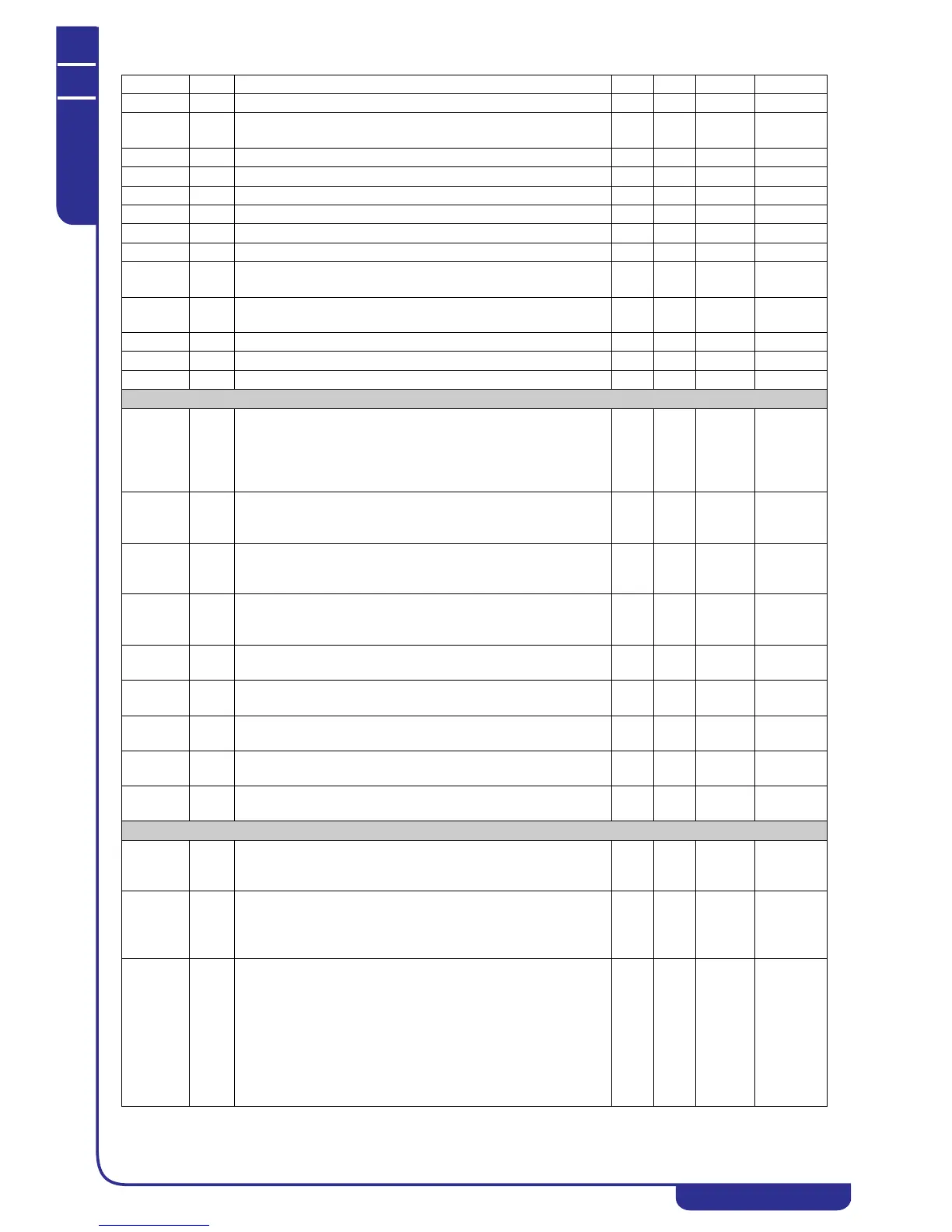
ES24 C End of time band 3 - domestic hot water (0...24) 0 24.00 by Hours 10 Min
ES25 C Monday: energy saving active
Monday operation with domestic hot water time band
07
ES26 C Tuesday operation with domestic hot water time band 0 7
ES27 C Wednesday operation with domestic hot water time band 0 7
ES28 C Thursday operation with domestic hot water time band 0 7
ES29 C Friday operation with domestic hot water time band 0 7
ES30 C Saturday operation with domestic hot water time band 0 7
ES31 C Sunday operation with domestic hot water time band 0 7
ES32 C Domestic hot water energy saving setting increase -30.0
-54
30.0
54
°C
°F
Dec
Int
ES33 C Domestic hot water differential in time band/digital input 0.1
0
25.0
45
°C
°F
Dec
Int
Pr1 U User password 0 999
Pr2 S Service password 0 999
Pr3 C Manufacturer password 0 999
Compressors plant
Cr01 C Defines the cooling plant temperature control type:
0= Disabled
1= Control with probe defined by ST09
2= Enabled with suction probe (evaporation) (condensing units
and heat pumps are automatically disabled)
02
Cr02 C Suction probe compressors setpoint (evaporation)
Makes it possible to program the working setpoint of the suction
probe
Cr03 Cr04 Bar
Psi
Dec
Int
Cr03 C Suction probe compressors minimum setting (evaporation)
Establishes the minimum limit that can be utilised to set the
suction probe working setpoint.
0 Cr02 Bar
Psi
Dec
Int
Cr04 C Suction probe compressors maximum setting (evaporation)
Establishes the maximum limit that can be utilised to set the
suction probe working setpoint.
Cr02 50
725
Bar
Psi
Dec
Int
Cr05 C Control steps activation band of suction probe. 0.1
1
14.0
203
Bar
Psi
Dec
Int
Cr06 C Energy saving setting increase in cooling plant mode. 0.0
0
14.0
203
Bar
Psi
Dec
Int
Cr07 C Energy saving differential in cooling plant mode. 0.1
1
14.0
203
Bar
Psi
Dec
Int
Cr08 C No. of compressors to start in case of fault of probe allocated for
their control 0 ... 6
06
Cr09 C No. of condensing fan steps of the circuit to activate in case of
fault of probe allocated for their control 0 ... 4
04
Compressor
CO01 C Compressor minimum run time.
Establishes the time during which the compressor must run after
being starting, even if the demand drops.
0 250 10 Sec 10 Seconds
CO02 C Compressors minimum stop time.
Establishes the time during which the compressor must remain
stopped, even if restarting is requested.
During this period the compressor LED will flash.
0 250 10 Sec 10 Seconds
CO03 C Time lag between starts of 2 compressors / capacity steps.
With two compressors, establishes the starting time lag between
the two in order to limit starting peak current.
During this period the compressor LED will flash (only for the
compressor).
With unit having one capacity controlled compressor.
Establishes the activation time of the capacity control solenoid
for a start at minimum capacity (see heading “7.15.1 Compressors
control”).
1 250 Sec
Parameter Level Description Min. Max. UM Resolution