OPERATING AND MAINTENANCE MANUAL
Chapter 7 - Electronic controller
TAEevo Tech 015÷802 60 Hz UL
84
The data in this manual are not binding and they can be modified by the manufacturer without notice. Reproduction of this manual is strictly prohibited
ENGLISH
EN
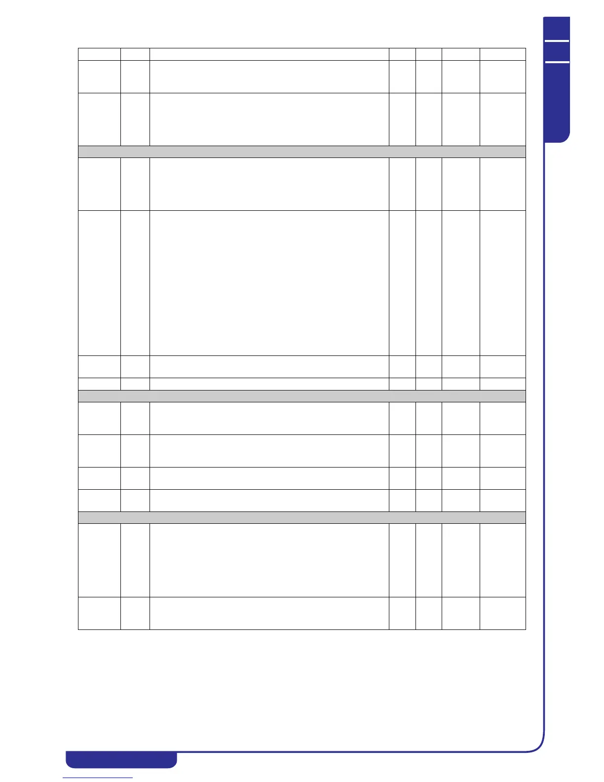
CO04 C Time lag between stops of 2 compressors / capacity steps.
Establishes the stopping time lag between two compressors or
two capacity steps.
0250Sec
CO05 C Delay at compressors starting from power ON.
Starting construed as physical power-up of the controller.
Delays activation of all the outputs to distribute current draw and
protect the compressor(s) from repeated starts in the event of
frequent mains power losses.
0 250 10 Sec 10 Seconds
Capacity controls (INACTIVE FUNCTION)
CO06 C Capacity controls operation:
0= ON/OFF steps control
1= Direct action continuous run with capacity steps
2= Reverse action continuous run with capacity steps
3= Global continuous capacity step control
03
CO07 C Enabling for operation of minimum compressor capacity /
unloaded starting management:
0= Enables minimum capacity only at compressor start (start with
minimum capacity / unloaded starting with valve OFF and
compressor stopped)
1= Enables minimum capacity only at compressor start and during
temperature control (start with minimum capacity / unloaded
starting with valve OFF and compressor stopped)
2= Screw compressors, enables minimum capacity only at
compressor start (start with minimum capacity / unloaded starting
with valve ON and compressor stopped)
3= Screw compressors, enables minimum capacity at compressor
start and during temperature control (start with minimum capacity
/ unloaded starting with valve ON and compressor stopped)
03
CO08 C Screw compressor intermittent valve control relay ON time; if
parameter value is 0 the function is disabled.
0250Sec
CO09 C Screw compressor intermittent valve control relay OFF time. 0 250 Sec
Compressor starting
CO10 C Compressor starting (see heading “7.15.1 Compressors control”):
0= Direct
1= Part-winding
01
CO11 CIf CO10=1 part-winding starting time. Used to vary the
energization of the two different relays that feed the two motor
windings.
0 100 Dec Sec 0.1 Sec
CO12 C Time for which condensation fan thermal protection switch is
bypassed after controller power on
0250Sec
CO13 C Run time with gas by-pass valve / compressor unloaded starting
valve (see capacity controls operation).
0250Sec
Compressors rotation - balancing - temperature control
CO14 S Compressors rotation (see heading “7.15.6 Compressors
rotation”):
0= Fixed sequence
1= Rotation enabled with compressors temperature control on
basis of running hours
2= Rotation enabled with compressors temperature control on
basis of starts/hour (peak loads)
02
CO15 S Circuits balancing:
0= Circuits saturation
1= Circuits balancing
01
Parameter Level Description Min. Max. UM Resolution