OPERATING AND MAINTENANCE MANUAL
Chapter 7 - Electronic controller
TAEevo Tech 015÷802 60 Hz UL
88
The data in this manual are not binding and they can be modified by the manufacturer without notice. Reproduction of this manual is strictly prohibited
ENGLISH
EN
CO92 C Advance of water side solenoid valve activation with respect to
compressor start
0250Sec
CO93 C Time lag of water side solenoid valve activation with respect to
compressor stop
0250Sec
CO94 C % compressor inverter output in defrosting 0 100 %
CO95 C FC pump hours set 0 999 10 Hours
CO96 C Inverter compressor analogue output value in unloading 0 100 %
Pr1 U User password 0 999
Pr2 S Service password 0 999
Pr3 C Manufacturer password 0 999
Circuit 1 auxiliary relay
US01 C Auxiliary relay 1 operation(see paragraph “7.17 Fans control”):
0= Not enabled
1= Direct action always enabled
2= Direct action enabled only with unit in ON
3= Reverse action always enabled
4= Reverse action enabled only with unit in ON
04
US02 C Configuration of analogue input for management of circuit 1
auxiliary relay makes it possible to choose probe from PB1 to
PB10 for management of the function
120
US03 C Auxiliary relay 1 output minimum summer set -50.0
-58
US5 °C
°F
Dec
Int
US04 C Auxiliary relay 1 output maximum summer set US5 110.0
230
°C
°F
Dec
Int
US05 C Auxiliary relay 1 output summer setpoint US3 US4 °C
°F
Dec
Int
US06 C Auxiliary relay 1 output winter minimum setpoint -50.0
-58
US8 °C
°F
Dec
Int
US07 C Auxiliary relay 1 output winter maximum setpoint US8 110.0
230
°C
°F
Dec
Int
US08 C Auxiliary relay 1 output winter setpoint US6 US7 °C
°F
Dec
Int
US09 C Auxiliary relay 1 summer differential 0.1
0
25.0
45
°C
°F
Dec
Int
US10 C Auxiliary relay 1 winter differential 0.1
0
25.0
45
°C
°F
Dec
Int
Circuit 2 auxiliary relay
US11 C Auxiliary relay 2 operation:
0= Not enabled
1= Direct action always enabled
2= Direct action enabled only with unit in ON
3= Reverse action always enabled
4= Reverse action enabled only with unit in ON
04
US12 C Configuration of analogue input for management of circuit 2
auxiliary relay makes it possible to choose probe from PB1 to
PB10 for management of the function
120
US13 C Auxiliary relay 2 output minimum summer set -50.0
-58
US15 °C
°F
Dec
Int
US14 C Auxiliary relay 2 output maximum summer set US15 110.0
230
°C
°F
Dec
Int
US15 C Auxiliary relay 2 output summer setpoint US13 US14 °C
°F
Dec
Int
US16 C Auxiliary relay 2 output winter minimum setpoint -50.0
-58
US18 °C
°F
Dec
Int
US17 C Auxiliary relay 2 output winter maximum setpoint US18 110.0
230
°C
°F
Dec
Int
US18 C Auxiliary relay 2 output winter setpoint US16 US7 °C
°F
Dec
Int
US19 C Auxiliary relay 2 summer differential 0.1
0
25.0
45
°C
°F
Dec
Int
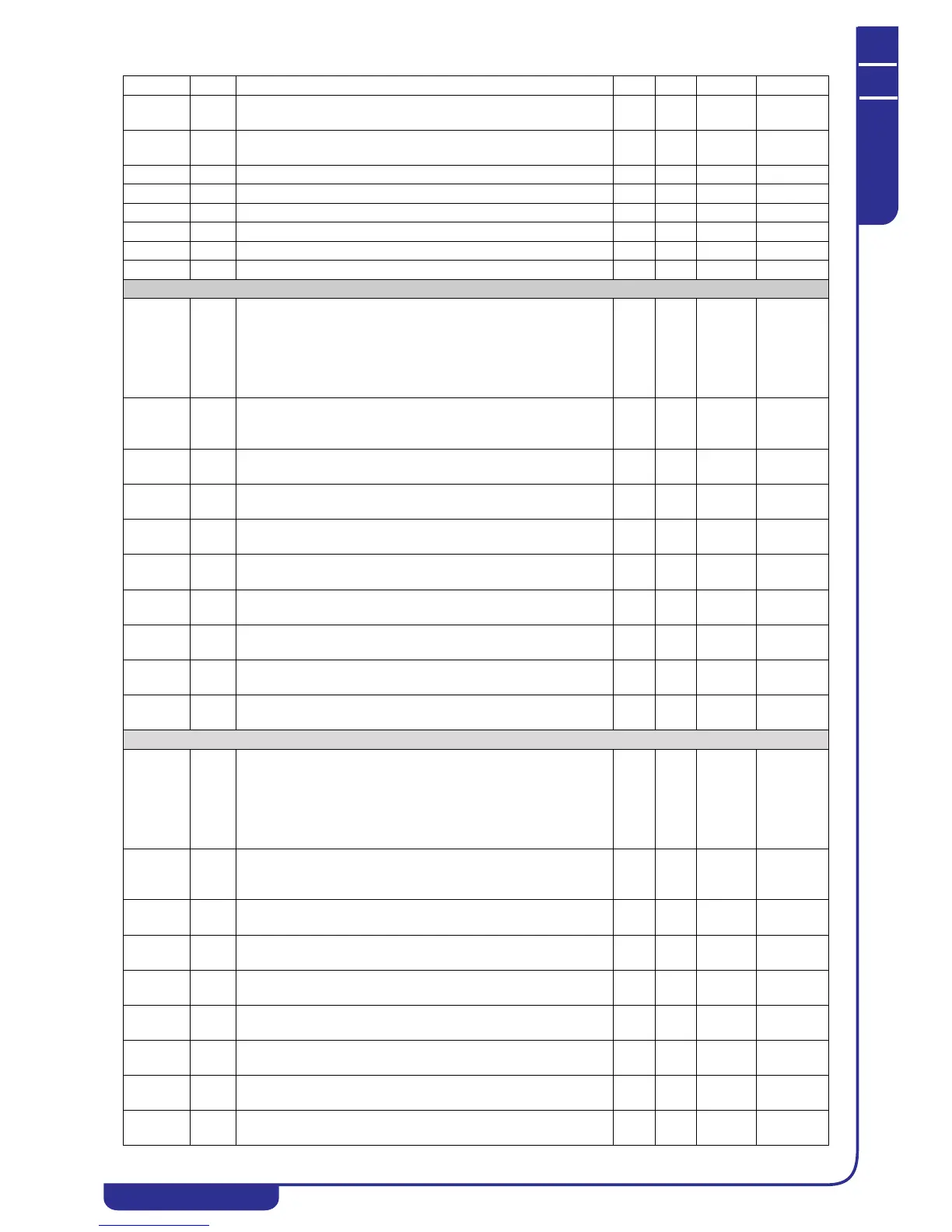
Parameter Level Description Min. Max. UM Resolution