OPERATING AND MAINTENANCE MANUAL
Chapter 7 - Electronic controller
TAEevo Tech 015÷802 60 Hz UL
93
The data in this manual are not binding and they can be modified by the manufacturer without notice. Reproduction of this manual is strictly prohibited
EN
ENGLISH
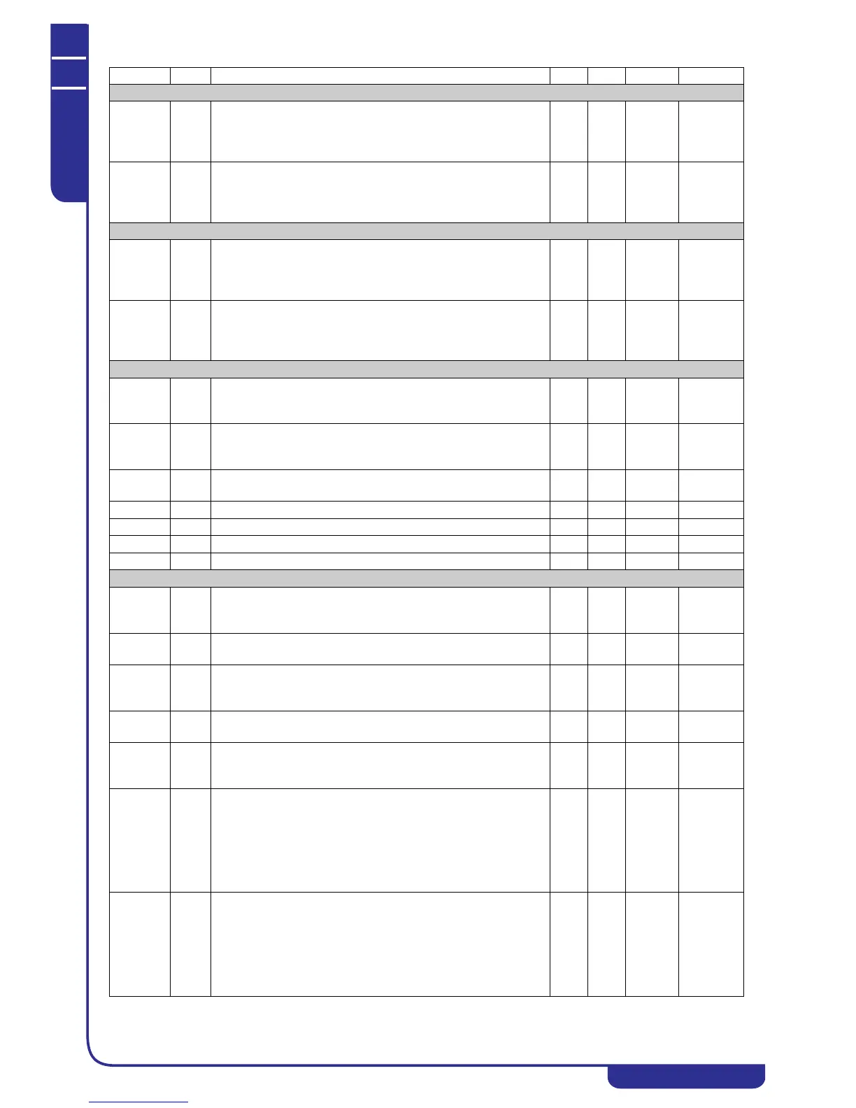
3-4 Fans step (chiller mode operation)
FA26 C Step control
3rd STEP SET Used to set the condensing temperature / pressure
value in chiller mode to which operation in ON corresponds of the
relay output configured as 3rd condensing fan speed step.
0.0
0
50.0
725
Bar
Psi
Dec
Int
FA27 C Step control
4th STEP SET Used to set the condensing temperature / pressure
value in chiller mode to which operation in ON corresponds of the
relay output configured as 4th condensing fan speed step.
0.0
0
50.0
725
Bar
Psi
Dec
Int
3-4 Fans step (heat pump mode operation)
FA28 C Step control
3rd STEP SET Used to set the condensing temperature / pressure
value in heat pump mode to which operation in ON corresponds
of the relay output configured as 3rd condensing fan speed step.
0.0
0
50.0
725
Bar
Psi
Dec
Int
FA29 C Step control
4th STEP SET Used to set the condensing temperature / pressure
value in heat pump mode to which operation in ON corresponds
of the relay output configured as 4th condensing fan speed step.
0.0
0
50.0
725
Bar
Psi
Dec
Int
Pre-ventilation in heat pump mode
FA30 C Pre-ventilation in heat pump mode.
Used to set a run time of the fans at maximum speed in Heat
pump mode before starting of the compressor (only if FA01 = 4)
0 250 Sec Sec
FA31 C Post-ventilation in heat pump mode.
Used to keep the fan running for a certain period after
stopping of the compressor
0 250 Sec 10Sec
FA32 C Ambient air temperature for post-ventilation in heat pump mode -50.0
-58
110.0
230
°C
°F
Dec
int
FA33 C Fans speed during post-ventilation 0 100 %
Pr1 U User password 0 999
Pr2 S Service password 0 999
Pr3 C Manufacturer password 0 999
Anti-freeze - support - water heater elements
Ar01 S Anti-freeze heaters setpoint (air/air unit) in chiller mode.
Used to set a temperature value below which the anti-freeze
heaters are switched on
-50.0
-58
110.0
230
°C
°F
Dec
Int
Ar02 S Anti-freeze / support heaters regulation band range in chiller
mode
0.1
0
25.0
45
°C
°F
Dec
Int
Ar03 C Support heaters setpoint (air/air unit) in heat pump mode.
Used to set a temperature value below which the anti-freeze
heaters are switched on
-50.0
-58
110.0
230
°C
°F
Dec
Int
Ar04 C Anti-freeze / support heaters regulation band range in heat pump
mode
0.1
0
25.0
45
°C
°F
Dec
Int
Ar05 C Operation of anti-freeze / support heaters in defrost:
0= Activated only by thermoregulator
1= Activated by thermoregulator and during defrost cycle
01
Ar06 C Anti-freeze / support heaters thermoregulation probe in chiller
mode:
0= Disabled
1= Regulation on evaporator inlet
2= Regulation on evaporator outlet 1 / 2
3= Regulation on evaporator outlet 1 / 2 and common outlet
4= Regulation on ambient air temperature
04
Ar07 C Anti-freeze / support heaters thermoregulation probe in heat
pump mode:
0= Disabled
1= Regulation on evaporator inlet
2= Regulation on evaporator outlet 1 / 2
3= Regulation on evaporator outlet 1 / 2 and common outlet
4= Regulation on ambient air temperature
04
Parameter Level Description Min. Max. UM Resolution