OPERATING AND MAINTENANCE MANUAL
Chapter 7 - Electronic controller
TAEevo Tech 015÷802 60 Hz UL
95
The data in this manual are not binding and they can be modified by the manufacturer without notice. Reproduction of this manual is strictly prohibited
EN
ENGLISH
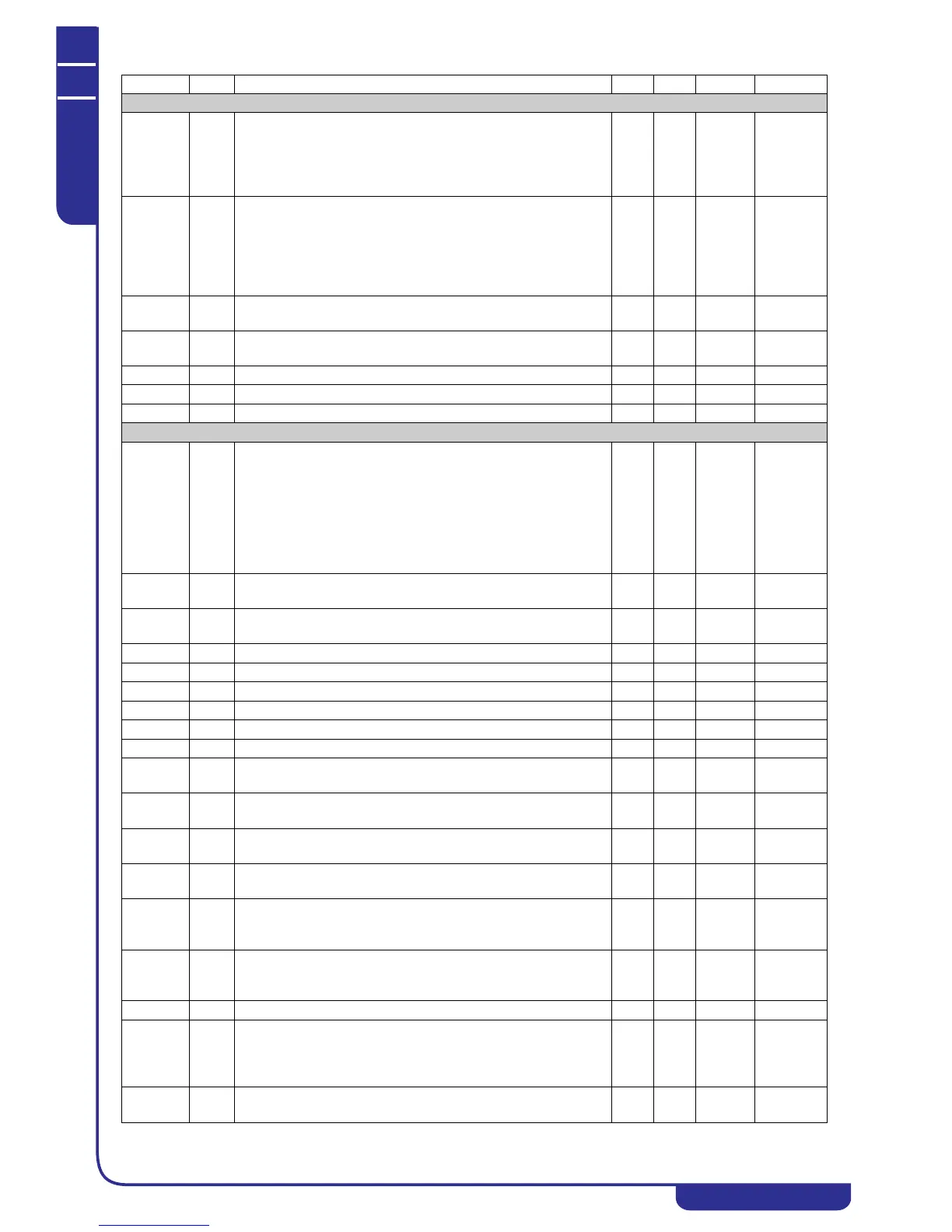
Evaporator water pump operation with anti-freeze alarm
Ar24 S Causes pump/s to start for anti-freeze when device is OFF or on
Stand-by:
0= Always off in remote OFF or Stand-by
1= On in remote OFF or Stand-by (switched on in accordance
with thermoregulator request)
01
Ar25 C Pump/s operation thermoregulation probe for anti-freeze:
0= Disabled
1= Regulation on evaporator inlet
2= Regulation on evaporator outlet 1 / 2
3= Regulation on evaporator outlet 1 / 2 and common outlet
4= Regulation on Ambient Air Temp.
04
Ar26 C Pump activation setpoint in anti-freeze operation on
thermoregulation probe
-50.0
-58
110.0
230
°C
°F
Dec
Int
Ar27 C Pump deactivation differential in anti-freeze operation on
thermoregulation probe
0.1
0
25.0
45.0
°C
°F
Dec
Int
Pr1 U User password 0 999
Pr2 S Service password 0 999
Pr3 C Manufacturer password 0 999
Defrosting
dF01 C Defrost modes:
0= Defrosting disabled
1= Temperature / pressure
2= Start depends on value of par. dF24 end by time
3= Start depends on value of par. dF24 end by external contact
4= With condensing fan
5= Start by external contact and end depending on value of par.
dF24
05
dF02 C Defrost start pressure / temperature. 0.0
0
50.0
725
Bar
Psi
Dec
Int
dF03 C Defrost end pressure / temperature. 0.0
0
50.0
725
Bar
Psi
Dec
Int
dF04 C Defrost minimum duration. 0 250 Sec
dF05 C Defrost maximum duration. 0 250 Min
dF06 C Time lag between defrosting of two circuits. 0 250 Min
dF07 C Wait time in compressor OFF before defrosting. 0 250 Sec
dF08 C Wait time in compressor OFF after defrosting. 0 250 Sec
dF09 C Defrosting interval on same circuit. 1 99 Min
dF10 C Temperature set for combined defrost cycle start, circuit no. 1
after count of parameter DF10.
-50.0
-58
110.0
230
°C
°F
Dec
Int
dF11 C Temperature set for combined defrost cycle end, circuit no. 1. -50.0
-58
110.0
230
°C
°F
Dec
Int
dF12 C Temperature set for combined defrost cycle start, circuit no. 2
after count of parameter DF10.
-50.0
-58
110.0
230
°C
°F
Dec
Int
dF13 C Temperature set for combined defrost cycle end, circuit no. 2. -50.0
-58
110.0
230
°C
°F
Dec
Int
dF14 C Forcing in ON activates all defrost steps in circuit no. 1:
0= Disabled
1= Enabled
01
dF15 C Forcing in ON activates all defrost steps in circuit no. 2:
0= Disabled
1= Enabled
01
dF16 C Starting time lag between two compressors in defrost. 0 250 Sec
dF17 C Enabling of fan ON during defrosting / dripping:
0= Disabled
1= Only defrost enabled
2= Defrost / dripping enabled
02
dF18 C Pressure / temperature set for forced ON of fans during defrost. 0.0
0
50.0
725
Bar
Psi
Dec
Int
Parameter Level Description Min. Max. UM Resolution