Supplement to the manual
MULTIPLEX Modellsport GmbH & Co.KG • Westliche Gewerbestraße 1 • D-75015 Bretten (Gölshausen) • www.multiplex-rc.de Page 21
7.1.1. Preparing the transmitter
1. Switch the transmitter on with the 3-D digi-adjuster
pressed in, then release the 3-D digi-adjuster. The
screen now displays the LO POW menu for the
range check:
The blue LED glows constantly:
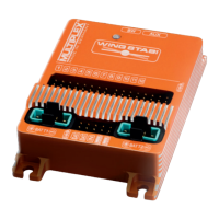
2. Turn the 3-D digi-adjuster to the right 3 until the
FRANCE menu appears:
3. Press the 3-D digi-adjuster briefly (r).
You will hear an audible signal, and the number on
the screen starts to flash.
4. Now you can use the 3-D digi-adjuster to set the
desired mode of operation:
0 = France mode = OFF
1 = France mode = ON
5. Press the 3-D digi-adjuster briefly (r) in order to
confirm you choice.
The on-screen number now ceases to flash.
6. Switch the transmitter OFF, and then ON again in
binding mode (Î 10.2.).
! Caution:
After any change to the FRANCE setting it is essential
to repeat the binding process with all the receivers you
intend to use with the transmitter (Î 10.2.).
9. The transmitter
9.5.1. Transmitter aerial
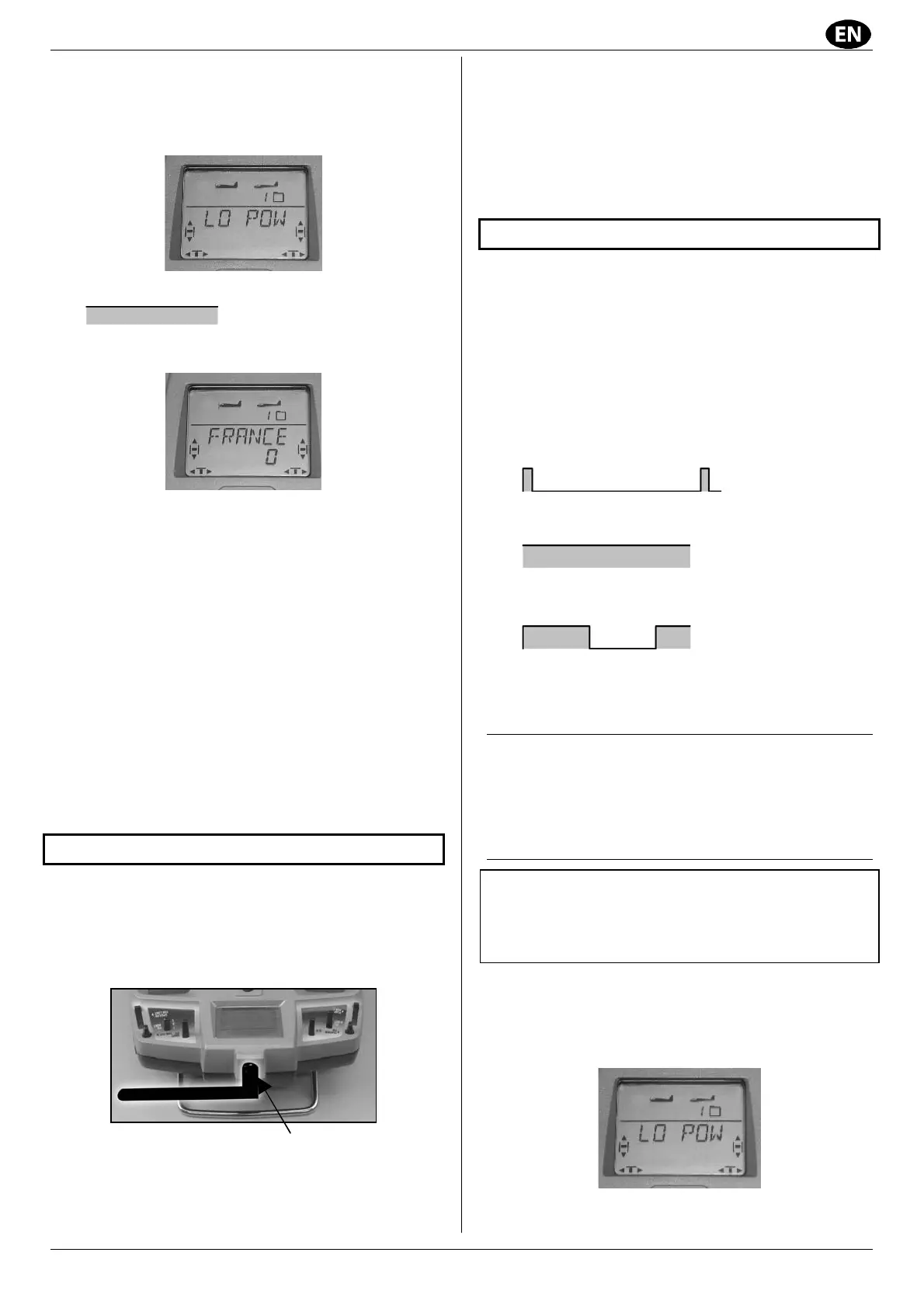
Once installed, the Cockpit SX M-LINK transmitter’s
2.4 GHz aerial can be tilted and rotated to either side.
When using the transmitter, angle the aerial at approxi-
mately 90° at the swivel joint, and tilt it horizon-tally to
left or right (see photo below):
Aerial in operating position; knurled nut
For applications where the model is not directly above
or below the transmitter (this applies in particular to
model cars and boats), the optimum transmitter aerial
position is pointing vertically upwards.
! Important:
Do not point the aerial straight at the model!
Never point the aerial directly at the model. For tech-
nical reasons the transmitted signal is at its weakest in
a straight line extending straight out from the aerial.
! At regular intervals check that the screwed aerial
joint (knurled nut) is firmly seated.
10. First use
Before the transmitter and receiver will work together
they must “learn” each other’s characteristics. This
procedure is known as “binding”.
Note: general information on the subject of binding,
and on fault-finding and correction as part of the bin-
ding procedure, can be found in the instructions
supplied with your MULTIPLEX M-LINK receiver.
Is the receiver already bound to the transmitter?
To check this, use the following procedure:
1. Switch the transmitter on:
Î the blue LED flashes:
2. Switch the receiver on:
Î the yellow LED glows constantly:
Binding required! (Î 10.2.).
Î the yellow LED flashes slowly:
Connection successful.
The system is ready for use.
10.1. Charging the transmitter battery
The Cockpit SX M-LINK is supplied with a partly charged
battery which must be given a full charge before the
transmitter is used for the first time. Please see the
notes regarding the transmitter battery (Î 8.).
10.2. The binding procedure
! Important: secure the model!
When the binding procedure is completed success-
fully, the system immediately starts working. This
could cause the motor to burst into life, so please
secure the model to avoid damage or injury.
10.2.1. Prepare the transmitter
1. Switch the transmitter on with the 3-D digi-adjuster
pressed in, and then release the 3-D digi-adjuster.
The screen now displays the range check menu
LO POW: