Vector-LP Radio Beacon Transmitter Technical Instruction Manual Page 5-8
Section 5 Maintenance and Troubleshooting Issue 1.1
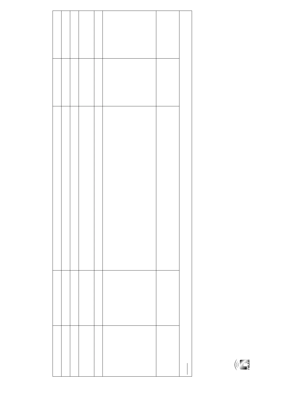
Table 5-1: Troubleshooting and Replacement Tips (Continued)
Front Panel
LED
Status
Message
Action
See Troubleshooting/
Replacement Paragraph
See Re-calibration
Paragraph
- - Replace the RF power probe (A15).
N/A 4.3.6.3
- - Replace the optional battery boost assembly (A16).
5.9 4.3.6.11 (if applicable)
- - Replace the modulator filter PWB (A4) of the applicable RF power module (A12 or A13).
5.6 3.6.13.4 (ensure the
replaced/repaired module is
on the standby side)
- - Replace the RF filter PWB (A14).
Tables 2-7a and 2-7b 4.3.6.2
- - Replace the control/display PWB (A1). Verify all jumper settings on the replacement PWB are the same as
the replaced PWB.
N/A 4.3.5.1
4.3.5.2
4.3.5.3 (if applicable)
4.3.5.5 (if applicable)
4.3.5.11
4.3.6.3 (single side) or
4.3.6.10 (dual side)
4.3.6.4
4.3.6.5
4.3.6.8
4.3.6.11 (if applicable)
4.3.6.12
- - Replace the remote interface PWB (A3). Verify all jumper settings on the replacement PWB are the same as
the replaced PWB.
N/A 4.3.5.4
4.3.5.9 (if applicable)
4.3.5.10 (if applicable)
4.3.5.11 (if applicable)
4.3.6.7
NOTE:
PWBs and assemblies that are not referenced in this table do not require special replacement or re-calibration procedures.