Page 3-24 Vector-LP Radio Beacon Transmitter Technical Instruction Manual
Issue 1.1 Section 3 Operating Instructions
x The first two values in each column are
internal tone generator reference values.
x The third and fourth values are the
modulation depth (in %) for PTT Inactive
and PTT Active respectively.
x Press Toggle to switch between RF
Mon: CURR and Rf Mon: VOLT, if
desired.
(j) Press Compute New Thresholds to
establish new monitor modulation %
thresholds.
(k) If a modification is made, a screen
appears which prompts you to save
changes to EEPROM. Select Yes or No.
3.6.8 Meter Settings
Determine the parameter to be displayed on
the front panel analog meter or the diagnostic
display’s meters screen as follows:
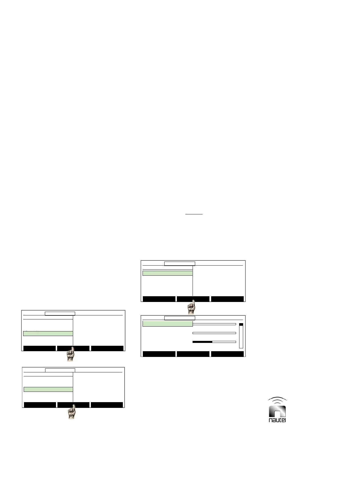
(a) From the main menu, highlight Settings
(using f and g) and press Select.
Highlight Meter Settings and press
Select. Use f and g to highlight
Change Meter Groups, Select Analog
Meter or Calib. Analog Meter and press
Select. Refer to the appropriate
paragraph (3.6.8.1 through 3.6.8.3 for
further details.
3.6.8.1 Changing Meter Groups
For monitoring and troubleshooting
convenience, the currently displayed meters
on the GUI’s meters screen can be changed
to display any three of the available meters:
Forward Power +5 V P/S
Reflected Power -15 V P/S
Modulation % PDM A or B
Modulation % A or B B+ Volts P/S A or B
VSWR PA Volts P/S A or B
Ac Voltage Dc Current P/S A or B
RF Current Temperature P/S A or B
Antenna Current Fan 1 Speed P/S A or B
Temperature Fan 2 Speed P/S A or B
ATU Temperature Battery Voltage
+24 V P/S Battery Current
+15 V P/S Charger Current
NOTE
Modulation % A and B refers to the
modulation read by monitor board A and B
respectively. Modulation % refers to the
active monitor board.
Set up the displayed parameters as follows:
(a) Use f and g to select the parameter to
be replaced and press Modify. Use f
and g to select the desired parameter to
be monitored in its place. Press Done to
activate the change. Press Back.
(b) A message appears to confirm saving
changes to the EEPROM. Press Yes or
No.
Forward Power: 0W
0 600 1200
Reflec. Power: 0.0W
0 100 200
VSWR: 1.00
01 2
12:43:16 Power: 0W Side A Bypass
Save Backup Modify Back
Forward Power: 0W
0 600 1200
Reflec. Power: 0.0W
0 100 200
VSWR: 1.00
01 2
12:43:16 Power: 0W Side A Bypass12:43:16 Power: 0W Side A Bypass
Save Backup Modify Back
Main Menu Select Back
12:43:16 Power: 0W Side A Bypass
Meter Settings
Change Meter Groups
Select Analog Meter
Calib. Analog Meter
Main Menu Select Back
12:43:16 Power: 0W Side A Bypass12:43:16 Power: 0W Side A Bypass
Meter Settings
Change Meter Groups
Select Analog Meter
Calib. Analog Meter
Select Meters
12:43:16 Power: 0W Side A Bypass
Main Menu
Changeover Control
Events Log
Settings
Peripherals
RCMS Settings
Vector NDB
rev 1. 0. 4. 1
Jul 27 2007
13:52:45
Nautel
Select Meters
12:43:16 Power: 0W Side A Bypass12:43:16 Power: 0W Side A Bypass
Main Menu
Changeover Control
Events Log
Settings
Peripherals
RCMS Settings
Vector NDB
rev 1. 0. 4. 1
Jul 27 2007
13:52:45
Nautel
Settings
Set Real Time Clock
Monitor Settings
Meter Settings
Power Source Select
Configure Sonalert
Main Menu Select Back
12:43:16 Power: 0W Side A Bypass
Settings
Set Real Time Clock
Monitor Settings
Meter Settings
Power Source Select
Configure Sonalert
Main Menu Select Back
12:43:16 Power: 0W Side A Bypass12:43:16 Power: 0W Side A Bypass