Page 3-34 Vector-LP Radio Beacon Transmitter Technical Instruction Manual
Issue 1.1 Section 3 Operating Instructions
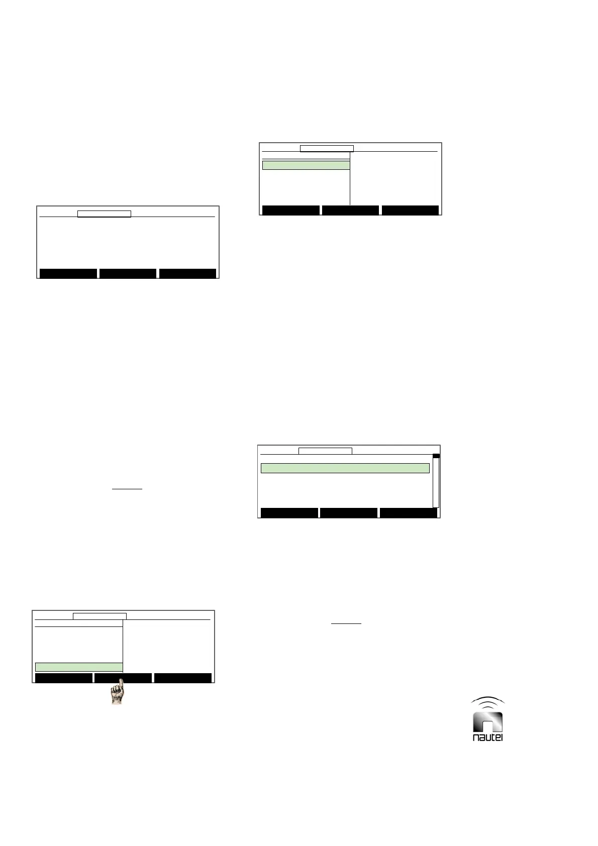
3.6.13.6 CHECKING MODULES:
Check the software revision of various
modules that contain microcontrollers as
follows:
(a) Use f and g to scroll through rows 1
to 12, noting:
x Rows 0 through 7 are assigned to RF
power modules.
x Rows 8 and 9 are assigned to the
exciter/monitor generator PWBs (side
A and, if applicable, side B).
x Row 10 is assigned to the associated
ATUs control/monitor PWB.
x Row 11 is assigned to the site control
PWB, if installed.
NOTE
If text is not displayed for a particular row,
the associated module or PWB is not
installed.
3.6.14 Remote Control Monitor
System Settings
If the NDB site interface PWB (A4) is
installed, configure the active logic states of
the control and monitor points as follows:
(a) From the main menu, highlight RCMS
Settings and press Select.
(b) Set the transmitter to Local mode.
(c) Press f or g to scroll through the
options and press Select to enter the
appropriate sub-menu (see paragraphs
3.6.14.1 through 3.6.14.3).
x Control Points (see 3.6.14.1)
x Monitor Points (see 3.6.14.2)
x Serial Settings (see 3.6.14.3)
x Automatic Reporting (see 3.6.14.4)
3.6.14.1 SETTING CONTROL POINTS
Set the site interface PWBs control points
as follows:
(a) Use f and g to highlight the desired
control point (1 through 16). Press
Toggle to change the logic level (0 or
1) of the Set Value. The logic level
determines the active state for the
control point’s remote input.
NOTE
Control points 1 through 16 correspond to
inputs connected to CONTROL POINT 1
through 16 on TB3 of the remote control/
monitor interface PWB.
(b) Return to previous menu by pressing
Back.
Main Menu Select Back
12:43:16 Power: 0W Side A Bypass
RCMS Settings
Control Points
Monitor Points
Serial Setting
Automatic Reporting
Main Menu Select Back
12:43:16 Power: 0W Side A Bypass12:43:16 Power: 0W Side A Bypass
RCMS Settings
Control Points
Monitor Points
Serial Setting
Automatic Reporting
Control Points Set Value
Control Point 1 0
Control Point 2 0
Control Point 3 0
Control Point 4 0
Control Point 5 0
Toggle Back
12:43:16 Power: 0W Side A Bypass
Control Points Set Value
Control Point 1 0
Control Point 2 0
Control Point 3 0
Control Point 4 0
Control Point 5 0
Toggle Back
12:43:16 Power: 0W Side A Bypass12:43:16 Power: 0W Side A Bypass
Select Meters
12:43:16 Power: 0W Side A Bypass
Main Menu
Changeover Control
Events Log
Settings
Peripherals
RCMS Settings
Vector NDB HP
rev 1. 0. 1. 2
Apr 24 2007
15:17:38
Nautel
Select Meters
12:43:16 Power: 0W Side A Bypass12:43:16 Power: 0W Side A Bypass
Main Menu
Changeover Control
Events Log
Settings
Peripherals
RCMS Settings
Vector NDB HP
rev 1. 0. 1. 2
Apr 24 2007
15:17:38
Nautel
Module Check
7
8 NAPE76u rev 0. 0. 0. 2
9 NAPE76u rev 0. 0. 0. 2
10
11 NAPI80u rev 0. 1. 0. 34
Main Menu Select Back
12:43:16 Power: 0W Site A Bypass
Module Check
7
8 NAPE76u rev 0. 0. 0. 2
9 NAPE76u rev 0. 0. 0. 2
10
11 NAPI80u rev 0. 1. 0. 34
Main Menu Select Back
12:43:16 Power: 0W Site A Bypass12:43:16 Power: 0W Site A Bypass