Vector-LP Radio Beacon Transmitter Technical Instruction Manual Page 3-25
Section 3 Operating Instructions Issue 1.1
Meter Settings
Change Meter Groups
Select Analog Meter
Calib. Analog Meter
Main Menu Select Back
12:43:16 Power: 0W Side A Bypass
Meter Settings
Change Meter Groups
Select Analog Meter
Calib. Analog Meter
Main Menu Select Back
12:43:16 Power: 0W Side A Bypass12:43:16 Power: 0W Side A Bypass
Meter Settings
Change Meter Groups
Select Analog Meter
Calib. Analog Meter
Main Menu Select Back
12:43:16 Power: 0W Side A Bypass
Meter Settings
Change Meter Groups
Select Analog Meter
Calib. Analog Meter
Main Menu Select Back
12:43:16 Power: 0W Side A Bypass12:43:16 Power: 0W Side A Bypass
Select Analog Meter
Scale 0-400 P
PDM B: 0.00%
(
)
PDM A: 0.00% ( )
DC Curr B: 0.00A ( )
DC Curr B: 0.00A ( )
Choose Scale Select Back
12:43:16 Power: 0W Side A Bypass
Select Analog Meter
Scale 0-400 P
PDM B: 0.00%
(
)
PDM A: 0.00% ( )
DC Curr B: 0.00A ( )
DC Curr B: 0.00A ( )
Choose Scale Select Back
12:43:16 Power: 0W Side A Bypass12:43:16 Power: 0W Side A Bypass
Selected Parameter
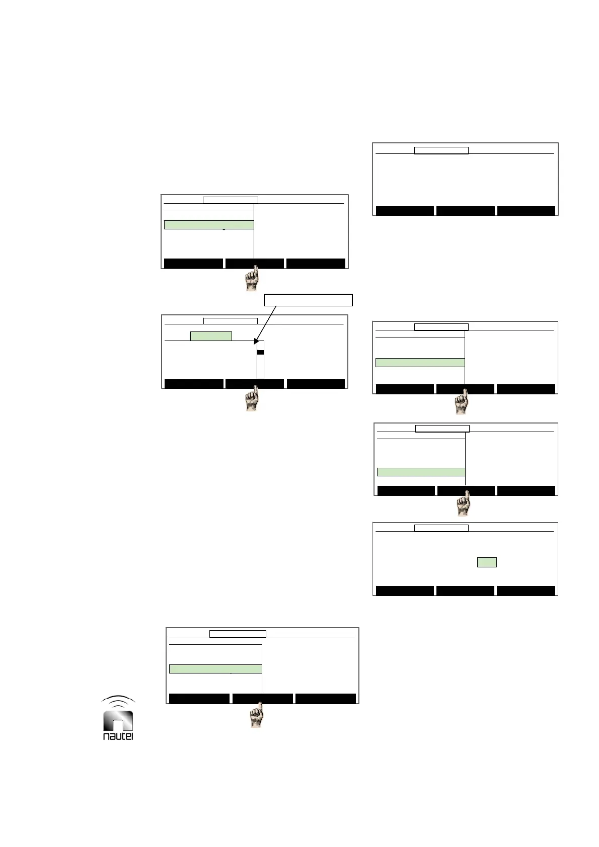
3.6.8.2 Selecting Analog Meter
Select the parameter to be displayed on the
front panel analog meter as follows:
(a) Use f or g to select the desired meter
parameter and press Select. Press
Choose Scale to select from various
scale options to view the parameter on
the front panel analog meter. Note that
scales with a P suffix are power (square
law) scales whereas scales with an L
suffix are linear scales.
(b) Press Back to return to the Meter
Settings screen. A message appears to
confirm saving changes to the EEPROM.
Press Yes or No.
3.6.8.3 Calibrating Analog Meter
Calibrate the analog meter as follows:
(a) When the analog meter is calibrated,
press Done.
3.6.9 Selecting Power Source
Select the transmitter’s power source and
view power source related parameters as
follows:
(a) From the main menu, highlight Settings
(using f and g) and press Select.
Highlight Power Source Select and
press Select.
(b) The parameters than can be modified
(press Modify and use f or g) are:
Select Meters
12:43:16 Power: 0W Side A Bypass
Main Menu
Changeover Control
Events Log
Settings
Peripherals
RCMS Settings
Vector NDB
rev 1. 0. 4. 1
Jul 27 2007
13:52:45
Nautel
Select Meters
12:43:16 Power: 0W Side A Bypass12:43:16 Power: 0W Side A Bypass
Main Menu
Changeover Control
Events Log
Settings
Peripherals
RCMS Settings
Vector NDB
rev 1. 0. 4. 1
Jul 27 2007
13:52:45
Nautel
Settings
Set Real Time Clock
Monitor Settings
Meter Settings
Power Source Select
Configure Sonalert
Main Menu Select Back
12:43:16 Power: 0W Side A Bypass
Settings
Set Real Time Clock
Monitor Settings
Meter Settings
Power Source Select
Configure Sonalert
Main Menu Select Back
12:43:16 Power: 0W Side A Bypass12:43:16 Power: 0W Side A Bypass
Power Source Select
DC I/F Instld: No
Active Power Source: AC
DC Disconnect Level: 14
DC Reconnect Level : 21
Requested Power Source:BOTH
Main Menu Modify Back
12:43:16 Power: 0W Side A Bypass
Power Source Select
DC I/F Instld: No
Active Power Source: AC
DC Disconnect Level: 14
DC Reconnect Level : 21
Requested Power Source:BOTH
Main Menu Modify Back
12:43:16 Power: 0W Side A Bypass
Press the up/down keys to adjust the
analog meter. The reading on the upper
scale should read 100.
(Midscale calibration constant:224)
Reset Done Cancel
12:43:16 Power: 0W Side A Bypass
Press the up/down keys to adjust the
analog meter. The reading on the upper
scale should read 100.
(Midscale calibration constant:224)
Reset Done Cancel
12:43:16 Power: 0W Side A Bypass12:43:16 Power: 0W Side A Bypass