Vector-LP Radio Beacon Transmitter Technical Instruction Manual Page 4-15
Section 4 Testing and Adjustment Issue 1.1
4.3.6.13 ADJUSTING SPEAKER
VOLUME
See Setting Protection Thresholds
(3.6.12.2). Adjust the Audio parameter as
desired.
4.3.6.14 READING MODULATION LEVEL
Read the modulation level as follows:
(a) Connect an oscilloscope to the RF
MONITOR connector (J8) on the
remote interface PWB (A3).
(b) Set the exciter in CW mode: use
and to scroll the display and set
Modulation to OFF using the Toggle
switch.
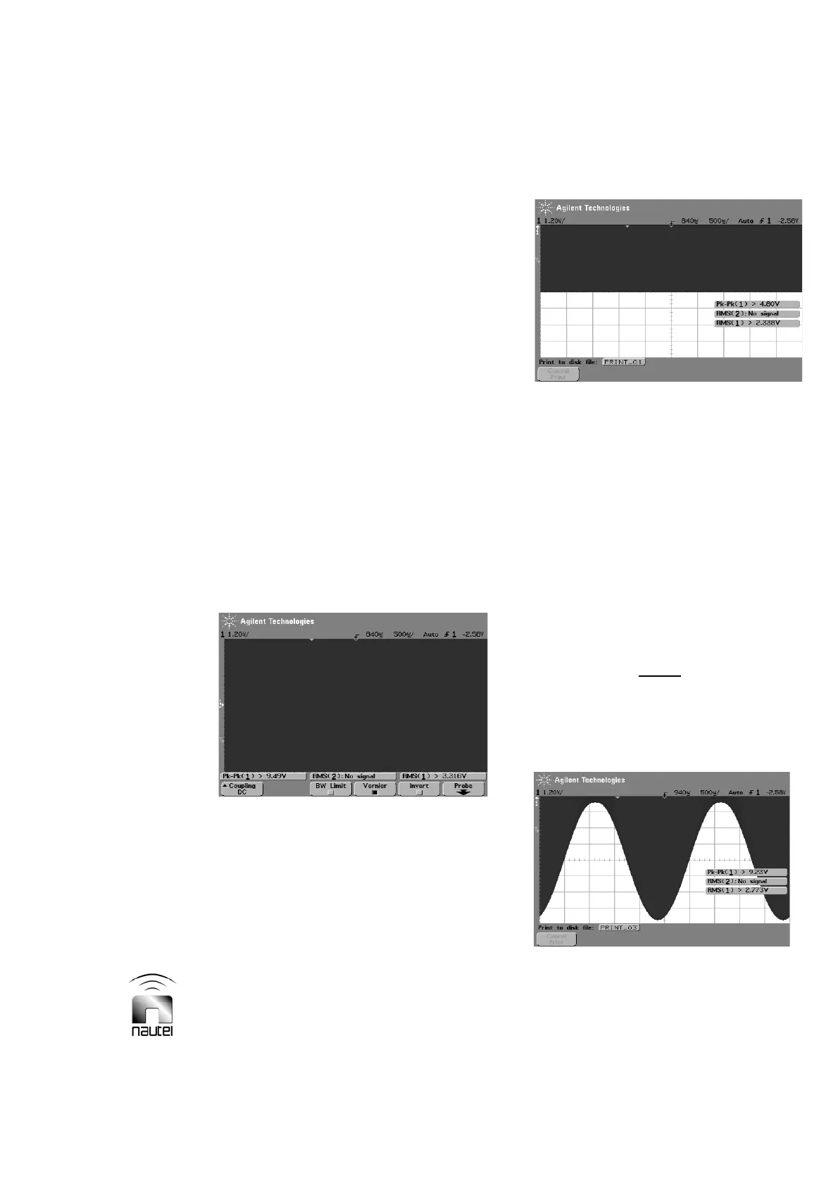
(c) Adjust the oscilloscope’s timescale to
500 Ps per division (for 400 Hz
modulation). Adjust the amplitude
level of the oscilloscope to just cover
all eight divisions of the display with
the RF signal (see Figure 4-2).
Figure 4-2: CW signal set to fill display
(d) Adjust the position of the oscilloscope
signal so that the bottom of the CW
waveform is at the mid-point of the
display (see Figure 4-3).
Figure 4-3: CW signal with position
adjusted to mid-point of display
(e) Set the exciter in MCW mode: use
and to scroll the display and set
Modulation to ON and the Keyer to
OFF using the Toggle switch.
(f) Measure the bottom of the waveform.
Each sub-division should correspond
to 5% in modulation. The bottom of
the waveform should be one sub-
division above the bottom of the
display when the modulation is at 95%
(see Figure 4-4).
NOTE
There may be some distortion in the
trough. This is an effect of class D
amplification called pinch off and can be
ignored as it does not produce significant
total harmonic distortion (THD).
Figure 4-4: MCW signal, 95% modulation