Page 3-4 Vector-LP Radio Beacon Transmitter Technical Instruction Manual
Issue 1.1 Section 3 Operating Instructions
3.5.2 Exciter Interface PWB
Controls and Indicators
Figure 3-4 and Table 3-3 identify and
describe the controls and indicators on the
exciter interface PWB (A2).
3.5.3 Remote Interface PWB
Controls and Indicators
Figure 3-5 and Table 3-4 identify and
describe the controls and indicators on the
remote interface PWB (A3).
3.5.4 RF Synthesizer PWB Controls
and Indicators
Figure 3-6 and Table 3-5 identify and
describe the controls and indicators on the
RF synthesizer PWBs (A5 and, if installed,
A8).
3.5.5 Miscellaneous Control and
Exciter Controls and Indicators
Table 3-6 describes the miscellaneous
controls and indicators of the control/
display PWB and exciter assemblies that
were not covered in previous paragraphs.
Refer to the mechanical drawings section
to locate a referenced item.
3.5.6 Miscellaneous RF Power
Stage Controls and Indicators
Table 3-7 describes the miscellaneous
controls and indicators of the RF power
modules (A12 and, If installed, A13). Refer
to the mechanical drawings section to
locate a referenced item.
3.5.7 Battery Boost PWB Controls
and Indicators
Figure 3-7 and Table 3-8 identify and
describe the controls on the optional
battery boost PWB (A16A1).
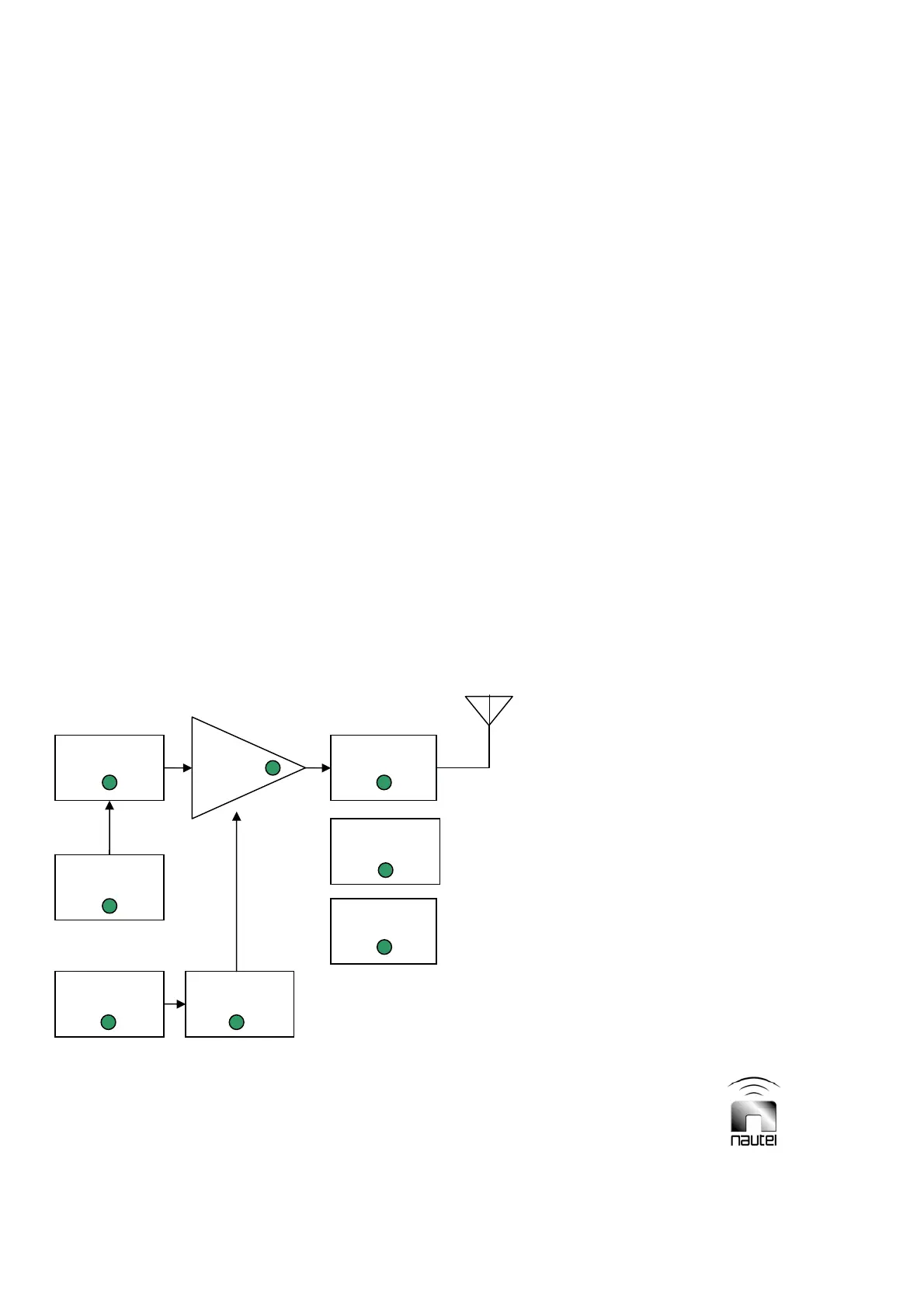
Figure 3-
2 Vector-LP Transmitter Front Panel – System Diagram Section
System Diagram
Output
Network
IPA/
PA
Exciter
Low Voltage
Power Supply
AC Mains Power Supply
External
Alarm
Changeover