Page 2-10 Vector-LP Radio Beacon Transmitter Technical Instruction Manual
Issue 1.1 Section 2 Preparation for Use and Installation
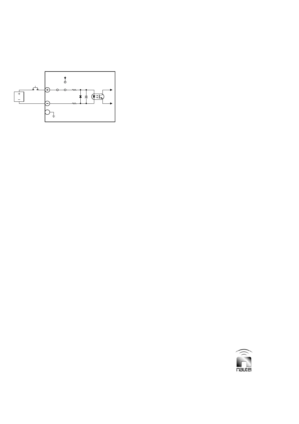
Figure 2-4 Differential Input Selected
Differential Input (External V dc)
When using an external dc voltage (24 V to
30 V) as the current source for a control
function’s opto-coupler, configure the control
function’s external switching circuit and the
remote interface PWB’s selection circuitry
for a differential input. Configure the 2-
socket shunt post on the 3-pin header
associated with the control function as
shown in Figure 2-4. The normally open/
held closed switch may be located between
the dc voltage's negative output and the
negative (-) input terminal (negative logic), or
between its positive output and the positive
(+) input terminal (positive logic).
2.2.12.1 On/Off Control
The remote on/off circuitry (TB1-5/6)
controls the on/off status of the RF power
stage. Activation of this circuit toggles the
status between on and off.
2.2.12.2 Charger Alarm
If an external battery charger is used, its
charger alarm output may be connected to
the transmitter (TB1-3/4) for fault monitoring.
2.2.12.3 Standby Code 1
The standby code 1 circuit (TB1-9/10)
controls the on/off status of standby code 1
generation.
2.2.12.4 Standby Code 2
The standby code 2 circuit (TB1-7/8)
controls the on/off status of standby code 2
generation.
2.2.13 Press-To-Talk Input
The press-to-talk circuit should be a normally
open, single pole switch. When closed
(press-to-talk), it should apply a ground to
TB1-12. If the press-to-talk information is
phantom fed on the audio shield (TB1-15),
the switching circuit is not required (see
jumper E4 in Table 3-4 and on Figure SD-11).
In phantom feed operation, -15 V must be
applied to the shield of the audio input when
press-to-talk is to be asserted.
2.2.14 User Assigned Information
Determine the final configuration of the
transmitter according to user requirements
and applications. Obtain the following user
assigned information prior to final assembly
and installation of the transmitter.
2.2.14.1 Carrier Frequency
Determine the transmitter's assigned carrier
frequency.
2.2.14.2 Keyed Tone Frequency
Determine which keyed tone frequency
(400 Hz, 1020 Hz or external) is to be used.
2.2.14.3 Identification Code
Determine the identification code that has
been assigned to the transmitter. Determine if
the programmable filler space after the last
character of the identification code is to be no
tone (CW) (ICAO) or continuous tone (MCW)
(NAVCAN).
2.2.14.4 Standby Codes
Determine the code variation to be
transmitted as standby '1', noting that options
consist of increasing one or more of the no-
tone intervals, between characters of the
identification code from 3 bits to 5 bits. When
the programmable filler space after the last
character is continuous tone, the no-tone
interval between the last character and the
continuous tone may be increased a similar
amount.
1
3
+24V
EXTERNAL DC
PWR SUPPLY
(+12V TO +30V)
E#
2
INTERFACE
PWB
REMOTE SELECTION CIRCUITRY
REMOTE
CONFIGURED FOR EXTERNAL
DC VOLTS
S1970004 V1
1