Vector-LP Radio Beacon Transmitter Technical Instruction Manual Page 3-33
Section 3 Operating Instructions Issue 1.1
ATU Control Antenna Curr.: 0.0A
Dec L N H Inc Auto-Tuning
R
[ ] [
][ ]
Active
L
[ ] [
][ ]
Active
Coil Control: Resistive Coil
What would you like to do:
12:43:16 Power: 0W Site A Bypass
Auto Tuning Slew Servo Back
ATU Control Antenna Curr.: 0.0A
Dec L N H Inc Auto-Tuning
R
[ ] [
][ ]
Active
L
[ ] [
][ ]
Active
Coil Control: Resistive Coil
What would you like to do:
12:43:16 Power: 0W Site A Bypass12:43:16 Power: 0W Site A Bypass
Auto Tuning Slew Servo Back
OR
(d) If Auto Tuning is selected, the
following screen appears which allows
the selected coil to be auto tuned
(active) or inhibited. Use f and g to
highlight Active or Inhibited, then
press Done to select.
(e) If Slew Servo is selected, the following
screen appears which allows the
selected coil to be manually tuned. Use
f and g to slew the coil high or low.
Press Done when complete.
3.6.13.4 TESTING THE STANDBY SIDE
Test the operation of the transmitter’s
inactive (standby) side as follows:
(a) Use f and g to highlight the desired
test (Turn Standby Side Off, Test
Power Supply, Test Modulators,
Test RF Drive, or Run All Tests).
Press Select to activate.
(b) If you select a test, the display will
initially indicate Running. When the
test is complete, a pass (OK) or fail
indication is displayed. If the item
under test fails, a root cause message
(e.g., PS Ovr Cur) is displayed.
NOTE
The root cause text is identical to that
displayed in the Status menu (see 3.6.3).
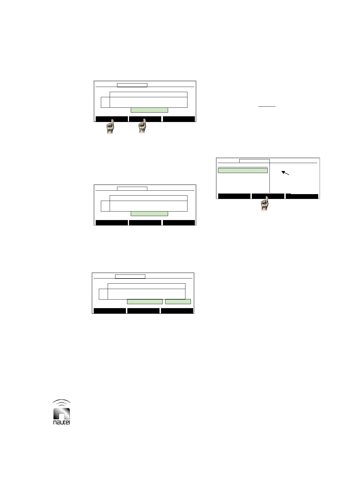
3.6.13.5 SELECTING PERIPHERALS
Configure the transmitter’s software for
peripheral equipment, such as an ATU or
site interface PWB as follows:
(a) Use f and g to highlight the desired
peripheral. Press Select to activate.
x If the site interface PWB (A2A4) is
installed, select Site Control Board.
x If a Nautel ATU is used and a serial
interface is connected to the
INTERNAL RS-485 connector on the
rear of the exciter/control assembly,
select ATU.
x To hear the sonalert buzzer for a fault
defined in the sonalert setup menu,
select SonAlert.
x To hear the transmitter output, select
Speaker.
x To enable the GUI to display Audio
Limit alarm occurrences, select
Overmod Alarm.
x If module fans are installed (VR250
only), select Module Fan Tachs.
(b) Return to previous menu by pressing
Back or press Main Menu.
ATU Control Antenna Curr.: 0.0A
Dec L N H Inc Auto-Tuning
R
[ ] [
][ ]
Active
L
[ ] [
][ ]
Active
Coil Control: Resistive Coil:Slew Servo
Up/Down Keys: Slew coil High/Low
12:43:16 Power: 0W Site A Bypass
Done
ATU Control Antenna Curr.: 0.0A
Dec L N H Inc Auto-Tuning
R
[ ] [
][ ]
Active
L
[ ] [
][ ]
Active
Coil Control: Resistive Coil:Slew Servo
Up/Down Keys: Slew coil High/Low
12:43:16 Power: 0W Site A Bypass12:43:16 Power: 0W Site A Bypass
Done
ATU Control Antenna Curr.: 0.0A
Dec L N H Inc Auto-Tuning
R
[ ] [
][ ]
Active
L
[ ] [
][ ]
Active
Coil Control: Resistive Coil
Up/Down Keys: (De)Activate Auto Tuning
12:43:16 Power: 0W Site A Bypass
Done
ATU Control Antenna Curr.: 0.0A
Dec L N H Inc Auto-Tuning
R
[ ] [
][ ]
Active
L
[ ] [
][ ]
Active
Coil Control: Resistive Coil
Up/Down Keys: (De)Activate Auto Tuning
12:43:16 Power: 0W Site A Bypass12:43:16 Power: 0W Site A Bypass
Done
Main Menu Select Back
12:43:16 Power: 0W Side A Bypass
Select Peripherals
Site Control Board
ATU
SonAlert Buzzer
Speaker
Overmod Alarm
[
]
[ ]
[ ]
[ ]
[ ]
Main Menu Select Back
12:43:16 Power: 0W Side A Bypass12:43:16 Power: 0W Side A Bypass
Select Peripherals
Site Control Board
ATU
SonAlert Buzzer
Speaker
Overmod Alarm
[
]
[ ]
[ ]
[ ]
[ ]
Indicates
Selected
Peripherals