Page 3-26 Vector-LP Radio Beacon Transmitter Technical Instruction Manual
Issue 1.1 Section 3 Operating Instructions
x DC Disconnect Level (DC power source
operation): if the dc power source is
below this voltage, the transmitter will
discontinue operation
x DC Reconnect Level (DC power source
operation): when the dc power source
recovers to this voltage, the transmitter
will attempt to restore operation.
x Requested Power Source: AC, DC,
BOTH (if both ac and dc power sources
are installed) or NONE.
(c) Press Done to activate. A message
appears to confirm saving changes to the
EEPROM. Press Yes or No.
(d) The remaining parameters are for
monitoring only.
x DC I/F Instld: Yes or No (indicates if
battery boost assembly A16 is installed).
x Active Power Source: indicates the power
source configuration for the transmitter
(AC, DC, BOTH or NONE)
3.6.10 Configuring the Sonalert
Configure the status of the audible alarm
(sonalert) for all transmitter alarms as follows:
(a) From the main menu, highlight Settings
(using f and g) and press Select.
Highlight Configure Sonalert and press
Select.
NOTE
The Sonalert peripheral must be activated
(see 3.6.13.5) before settings in this section
can take effect.
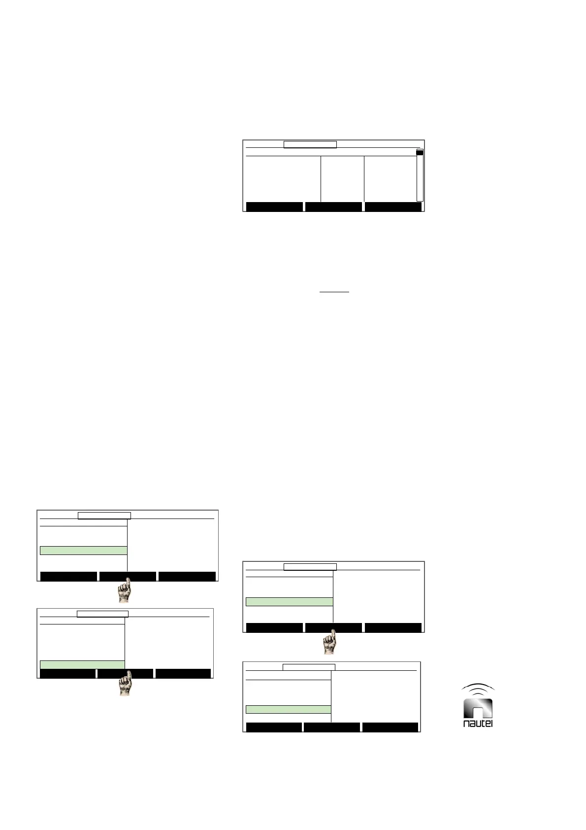
(b) A list of transmitter alarms and their
current SonAlert (audible) and Site Ctrl
(remote outputs) status is displayed.
x To configure an alarm for the sonalert,
use f and g to select the desired alarm;
press Toggle to change the status to ON.
x Press Modify to configure an alarm for
use with site interface PWB A4 (if
installed). Use f and g to select the
desired alarm and press Toggle to
change the status from OFF to the
appropriate remote control output (1
through 16).
3.6.11 Setting a Timed Shutdown
Modify timed shutdown parameters as
follows:
Select Meters
12:43:16 Power: 0W Side A Bypass
Main Menu
Changeover Control
Events Log
Settings
Peripherals
RCMS Settings
Vector NDB
rev 1. 0. 4. 1
Jul 27 2007
13:52:45
Nautel
Select Meters
12:43:16 Power: 0W Side A Bypass12:43:16 Power: 0W Side A Bypass
Main Menu
Changeover Control
Events Log
Settings
Peripherals
RCMS Settings
Vector NDB
rev 1. 0. 4. 1
Jul 27 2007
13:52:45
Nautel
Select Meters
12:43:16 Power: 0W Side A Bypass
Main Menu
Changeover Control
Events Log
Settings
Peripherals
RCMS Settings
Vector NDB
rev 1. 0. 4. 1
Jul 27 2007
13:52:45
Nautel
Select Meters
12:43:16 Power: 0W Side A Bypass12:43:16 Power: 0W Side A Bypass
Main Menu
Changeover Control
Events Log
Settings
Peripherals
RCMS Settings
Vector NDB
rev 1. 0. 4. 1
Jul 27 2007
13:52:45
Nautel
Settings
Set Real Time Clock
Monitor Settings
Meter Settings
Power Source Select
Configure Sonalert
Main Menu Select Back
12:43:16 Power: 0W Side A Bypass
Settings
Set Real Time Clock
Monitor Settings
Meter Settings
Power Source Select
Configure Sonalert
Main Menu Select Back
12:43:16 Power: 0W Side A Bypass12:43:16 Power: 0W Side A Bypass
Settings
Meter Settings
Power Source Select
Configure Sonalert
Timed Shutdown
Factory Settings
Main Menu Select Back
12:43:16 Power: 0W Side A Bypass
Settings
Meter Settings
Power Source Select
Configure Sonalert
Timed Shutdown
Factory Settings
Main Menu Select Back
12:43:16 Power: 0W Side A Bypass12:43:16 Power: 0W Side A Bypass
Toggle Modify Back
12:43:16 Power: 0W Side A Bypass
Alarm Signal SonAlert SiteCtrl
PDM Latch B OFF OFF
PDM Latch A OFF OFF
High RF Curr OFF OFF
SWR Shutback OFF OFF
Low AC Voltage OFF OFF
Toggle Modify Back
12:43:16 Power: 0W Side A Bypass12:43:16 Power: 0W Side A Bypass
Alarm Signal SonAlert SiteCtrl
PDM Latch B OFF OFF
PDM Latch A OFF OFF
High RF Curr OFF OFF
SWR Shutback OFF OFF
Low AC Voltage OFF OFF