Page 3-22 Vector-LP Radio Beacon Transmitter Technical Instruction Manual
Issue 1.1 Section 3 Operating Instructions
Monitor Timeout
Monitor Timeout Period:
20 seconds
Monitor Shutdown:
DISABLED
Main Menu Modify Back
12:43:16 Power: 0W Side A Bypass
Monitor Timeout
Monitor Timeout Period:
20 seconds
Monitor Shutdown:
DISABLED
Main Menu Modify Back
12:43:16 Power: 0W Side A Bypass12:43:16 Power: 0W Side A Bypass
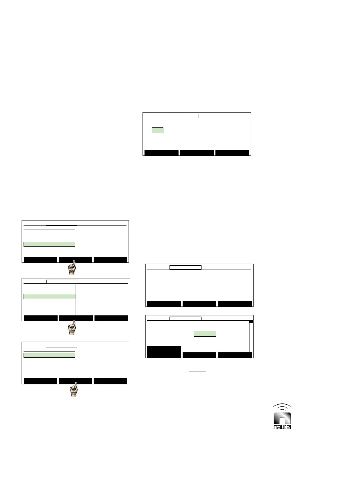
3.6.7 Setting RF Monitor Limits
High and low power thresholds, low
modulation threshold and loss of keying can
be set to ensure the transmitter is operating
within acceptable limits. If the RF carrier is
outside these limits for a pre-defined delay
period, the transmitter initiates a changeover
to the standby side (in normal operation) or
continues to operate (in bypass mode). Set
the transmitter’s RF monitor limits as follows:
NOTE
International Civil Aviation Organization
(ICAO) standards dictate the transmitter be
turned off or a warning alarm be generated
when the RF output decreases by 3.0 dB or
increases by 2.0 dB from the intended carrier
level. The user can alter the monitor settings
provided these criteria are still met.
(a) From the main menu, highlight Settings
and press Select. Highlight Monitor
Settings and press Select.
(b) Highlight Monitor Timeout and press
Select. See step (d) for Power
Thresholds.
(c) Use f and g to highlight the desired
monitor timeout field and press Modify:
x The monitor timeout period can be set
(using f and g) between 4 and 82 s
(factory set for 20 s).
x The monitor shutdown can be set (using
f and g) for ENABLED or DISABLED.
(d) Press Back, highlight Power
Thresholds and press Select. The
following message is displayed. Press
Continue to proceed.
NOTE
As the warning message indicates, ensure
that the transmitter is operating at the desired
power level before computing the new
thresholds. If the power level of the
transmitter changes after computing the
thresholds, re-establish the thresholds.
Before proceeding, make sure that you
have set the power level to your
Desired operating conditions.
Continue Back
12:43:16 Power: 0W Side A Bypass
Before proceeding, make sure that you
have set the power level to your
Desired operating conditions.
Continue Back
12:43:16 Power: 0W Side A Bypass12:43:16 Power: 0W Side A Bypass
Power Thresholds A B
Monitor Power Reading: 0 0
Low Power Limit: -2.99 dB 0 0
High Power Limit: 1.99 dB 0 0
Compute New
Thresholds
Modify Back
12:43:16 Power: 0W Side A Bypass
Power Thresholds A B
Monitor Power Reading: 0 0
Low Power Limit: -2.99 dB 0 0
High Power Limit: 1.99 dB 0 0
Compute New
Thresholds
Modify Back
12:43:16 Power: 0W Side A Bypass12:43:16 Power: 0W Side A Bypass
Main Menu Select Back
12:43:16 Power: 0W Side A Bypass
Monitor Settings
Monitor Timeout
Power Thresholds
Automatic Reset
Mod % Thresholds
Main Menu Select Back
12:43:16 Power: 0W Side A Bypass12:43:16 Power: 0W Side A Bypass
Monitor Settings
Monitor Timeout
Power Thresholds
Automatic Reset
Mod % Thresholds
Select Meters
12:43:16 Power: 0W Side A Bypass
Main Menu
Changeover Control
Events Log
Settings
Peripherals
RCMS Settings
Vector NDB
rev 1. 0. 4. 1
Jul 27 2007
13:52:45
Nautel
Select Meters
12:43:16 Power: 0W Side A Bypass12:43:16 Power: 0W Side A Bypass
Main Menu
Changeover Control
Events Log
Settings
Peripherals
RCMS Settings
Vector NDB
rev 1. 0. 4. 1
Jul 27 2007
13:52:45
Nautel
Settings
Set Real Time Clock
Monitor Settings
Meter Settings
Power Source Select
Configure Sonalert
Main Menu Select Back
12:43:16 Power: 0W Side A Bypass
Settings
Set Real Time Clock
Monitor Settings
Meter Settings
Power Source Select
Configure Sonalert
Main Menu Select Back
12:43:16 Power: 0W Side A Bypass12:43:16 Power: 0W Side A Bypass