Vector-LP Radio Beacon Transmitter Technical Instruction Manual Page 6-13
Section 6 Theory of Operation Issue 1.1
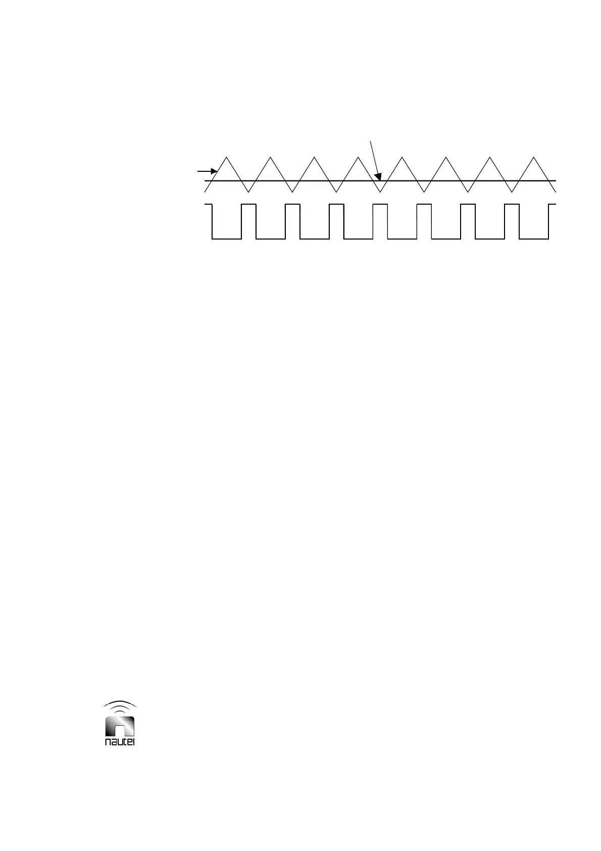
Figure 6-3 Timing Diagram for PDM Differential Amplifier
6.4.3.5 INTERPHASE PDM
GENERATOR
The interphase PDM generator consists of
two identical variable pulse duration
generators (PDM1 and PDM2; PDM1
circuitry is described). The PDM1
generator produces a 0 V to 15 V
rectangular waveform at the g
PDM
repetition rate. The waveform on/off ratio
(duty cycle) is directly proportional to the
carrier level. The transmitter uses three B+
voltage levels to maximize performance.
As the RF output power is increased from
0 W (B+ voltage is 55 V for VR125; 79 V
for VR250), the PDM duty cycle increases
proportionally. When the RF output is
increased so that the PDM duty cycle
reaches 45 %, the control/ display PWB
initiates a B+ voltage increase (to 97 V for
VR125; 136 V for VR250) and a PDM duty
cycle decrease (to 27%). When the RF
output is increased to a level where the
PDM duty cycle again reaches 45%, the
control/ display PWB initiates a B+ voltage
increase (to 167 V for VR125; 236 V for
VR250) and a PDM duty cycle decrease
(to 32%).
6.4.3.5.1 PDM1 Generator
The PDM1 generator consists of U10B,
transistors Q4, Q5, and associated
components. The compensated carrier
level ref input from the integrator peak
detector circuit is applied to differential
amplifier U10B's non-inverting input,
where it is compared to the triangular
waveform from the linear integrator circuit.
When the compensated carrier level ref is
more positive than the triangular
waveform, U10B's output is open collector.
+15 V is applied through R60 and R62 to
the balanced drive formed by Q4/Q5. Q4
turns on and applies +15 V to K1-3 as the
PDM1 output (Q5 is off). For the rest of the
triangular waveform's period, the
compensated carrier level ref is less
positive than the triangular waveform.
U10B's output is a current-sink-to -15 V
and Q4 turns off. Q5 turns on and clamps
the PDM1 output to ground. The minimum
'on time' (zero RF power) occurs at the
negative peaks of the triangular waveform.
See Figure 6-3 for a timing diagram.
PDM 1
Ramp
Carrier Reference
Level