Vector-LP Radio Beacon Transmitter Technical Instruction Manual Page 3-19
Section 3 Operating Instructions Issue 1.1
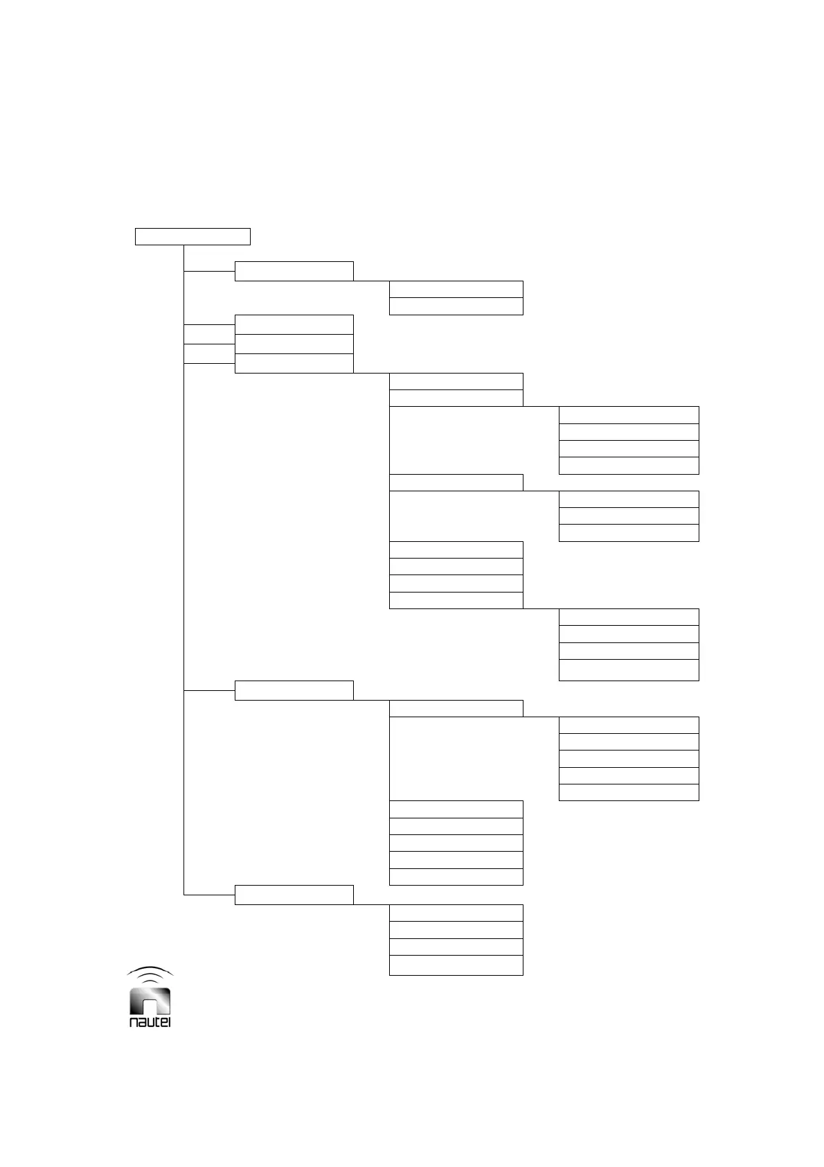
Diagnostic Display (GUI) Functions
(organized by menu hierarchy)
Reference
Paragraph
MAIN MENU
Meters
Status 3.6.3
Power 3.6.15
Changeover Control 3.6.4
Events Log 3.6.5
Settings
Set Real Time Clock 3.6.6
Monitor Settings 3.6.7
Monitor Timeout 3.6.7 (b)
Power Thresholds 3.6.7 (d)
Automatic Reset 3.6.7 (f)
Mod % Thresholds 3.6.7 (h)
Meter Settings 3.6.8
Change Meter Groups 3.6.8.1
Select Analog Meter 3.6.8.2
Calibrate Analog Meter 3.6.8.3
Power Source Select 3.6.9
Configure Sonalert 3.6.10
Timed Shutdown 3.6.11
Factory Settings
3.6.12
Calibrate Digital Meters 3.6.12.1
Set Thresholds 3.6.12.2
Maximum Output Gain 3.6.12.3
Use Factory Settings 3.6.12.4
Peripherals 3.6.13
Keyer Settings 3.6.13.1
Audio Levels 3.6.13.1 (a)
Keyer Modulation
3.6.13.1 (b)
Keyer Sequence
3.6.13.1 (c)
Standby Code 1
3.6.13.1 (d)
Standby Code 2
3.6.13.1 (d)
Power Modules 3.6.13.2
ATU Controls 3.6.13.3
Test Standby Side 3.6.13.4
Select Peripherals 3.6.13.5
Module Check 3.6.13.6
RCMS Settings 3.6.14
Control Points 3.6.14.1
Monitor Points 3.6.14.2
Serial Setting 3.6.14.3
Automatic Reporting 3.6.14.4
Figure 3-10 – Flow Diagram - Diagnostic Display Functions