Page 3-18 Vector-LP Radio Beacon Transmitter Technical Instruction Manual
Issue 1.1 Section 3 Operating Instructions
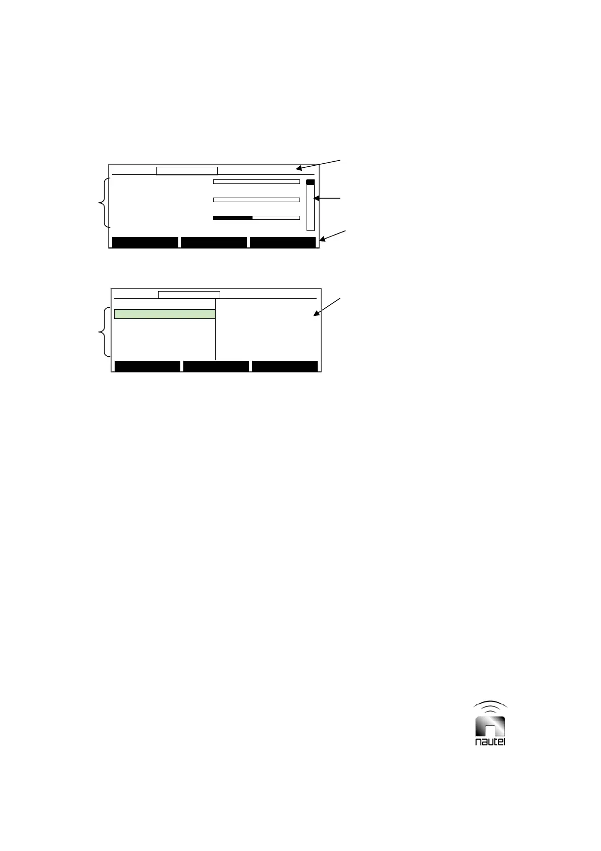
Figure 3-8 Diagnostic Display – Meters Screen
Figure 3-9 Diagnostic Display – Main Menu
3.6 DIAGNOSTIC DISPLAY
The diagnostic display (see Figure 3-9), in
the centre of the transmitter’s front panel, is
a 240 x 64 graphic LCD display and is the
primary local user interface for the
transmitter. With the exception of RF on/
off, power increase/decrease and local/
remote control, all transmitter functions can
be controlled and indicated by this display.
All critical parameters and events are
monitored from this display. The following
paragraphs describe how to use the
diagnostic display.
3.6.1 Pushbutton Switches
Navigating the diagnostic display is done
using the five pushbutton switches
adjacent the display. The up (f) and down
(g) pushbuttons, to the right of the display,
are used to move up and down through
displayed selections and to increase or
decrease the value of a selected
parameter. Pressing and holding the f or
g pushbutton will increase the rate of
change, where applicable. There are also
three soft-key pushbuttons whose
functions are defined by the text displayed
directly above them for a given menu.
3.6.2 Main Screens
The high level screens of the diagnostic
display (Figures 3-8 and 3-9) display:
x Transmitter status bar
x Three user-definable meter selections
x Meter selection scroll (controlled by f
and g pushbuttons)
x Sub-menu selections
x Software version
3.6.2.1 Transmitter Status Bar
The transmitter status bar is the
information displayed along the top of the
diagnostic display. This information is
present at all times and indicates the
following (from left to right):
x Current time (24-hour clock)
x Current output power
x Active side (A or B)
x Monitor mode (blank for normal or
Bypass) – bypass indicates that
automatic changeover is inhibited.
For quick reference, locate the desired
function in the flow diagram depicted in
Figure 3-10, then refer to the referenced
paragraph for further information.
Forward Power: 0W
0 600 1200
Reflec. Power: 0.0W
0 100 200
VSWR: 1.00
01 2
Main Menu Status Power
12:43:16 Power: 0W Side A Bypass
Forward Power: 0W
0 600 1200
Reflec. Power: 0.0W
0 100 200
VSWR: 1.00
01 2
Main Menu Status Power
12:43:16 Power: 0W Side A Bypass12:43:16 Power: 0W Side A Bypass
STATUS BAR
METER
SELECTION
SCROLL
SOFT KEY
LABELS
METER
SELECTIONS
SUB-MENU
SELECTIONS
SOFTWARE
VERSION
Select Meters
12:43:16 Power: 0W Side A Bypass
Main Menu
Changeover Control
Events Log
Settings
Peripherals
RCMS Settings
Vector NDB
rev 1. 0. 4. 1
Jul 27 2007
13:52:45
Nautel
Select Meters
12:43:16 Power: 0W Side A Bypass12:43:16 Power: 0W Side A Bypass
Main Menu
Changeover Control
Events Log
Settings
Peripherals
RCMS Settings
Vector NDB
rev 1. 0. 4. 1
Jul 27 2007
13:52:45
Nautel