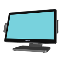
Product Overview 1-37
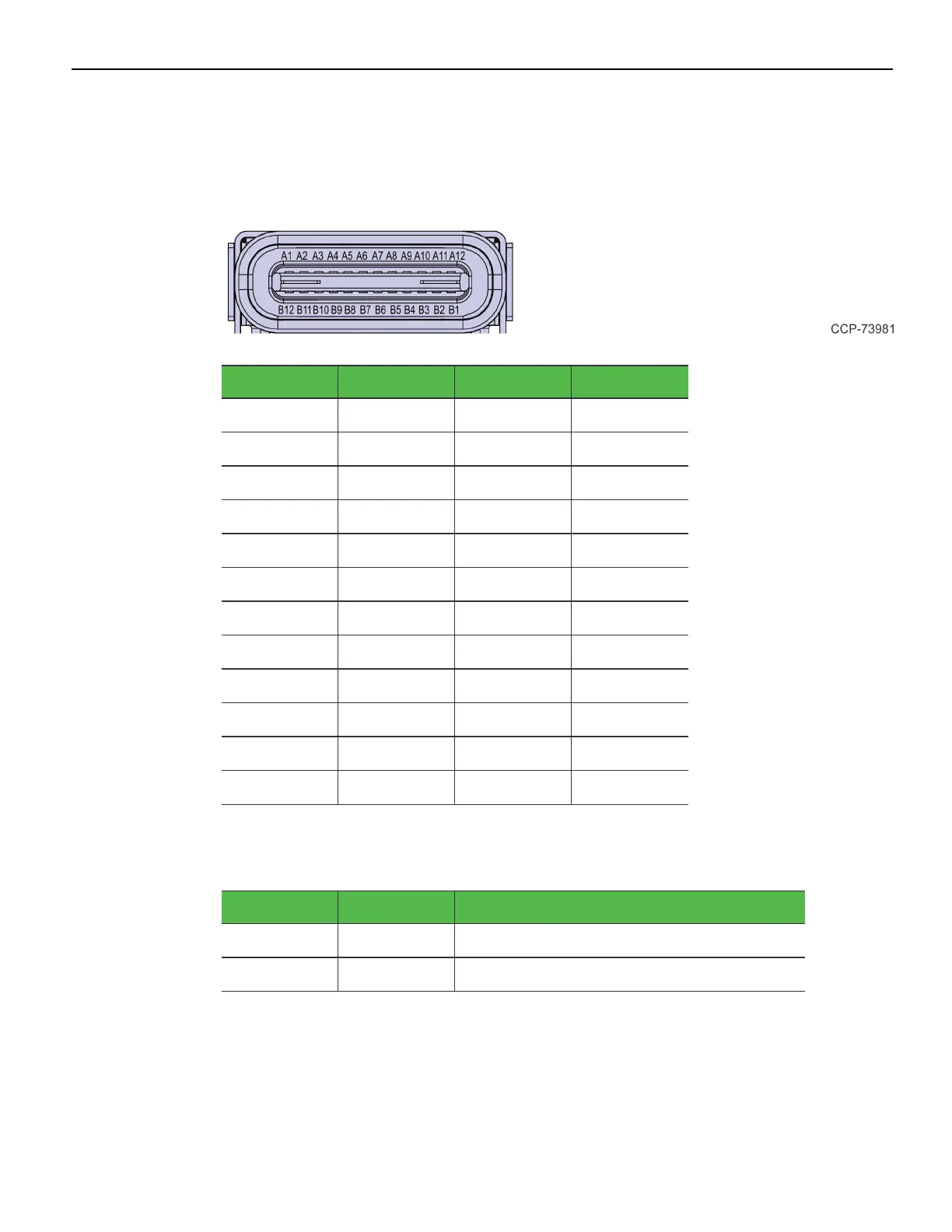
USB-C
The I/O Board is connected to the motherboard through a non-standard USB Type C
connector. The I/O Board provides a +24V power to the motherboard through the VBUS
lines of the USB-C connector.
Signal Pin Pin Signal
GND A1 B12 GND
USB3.0 TX1+ A2 B11 USB3.0 RX1+
USB3.0 TX1– A3 B10 USB3.0 RX1–
+V (24V) A4 B9 +V (24V)
CC1 (GPIO1) A5 B8 SBU2
USB2.0 A D+ A6 B7 USB2.0 BD–
USB2.0 A D– A7 B6 USB2.0 BD+
SBU1 A8 B5 CC2 (GPIO2)
+V (24V) A9 B4 +V (24V)
Display Port A10 B3 Display Port
Display Port A11 B2 Display Port
GND A12 B1 GND
Since reversibility is not required, the CC1 and CC2 signals will be re-purposed for the
following functions:
Signal Pin Function
CC1 (GPIO1) A5 Power Status from Motherboard
CC2 (GPIO2) B5 Display Port Hot Plug Detect

 Loading...