9-14
“Confidential, Do Not Duplicate without written authorization from NEC.”
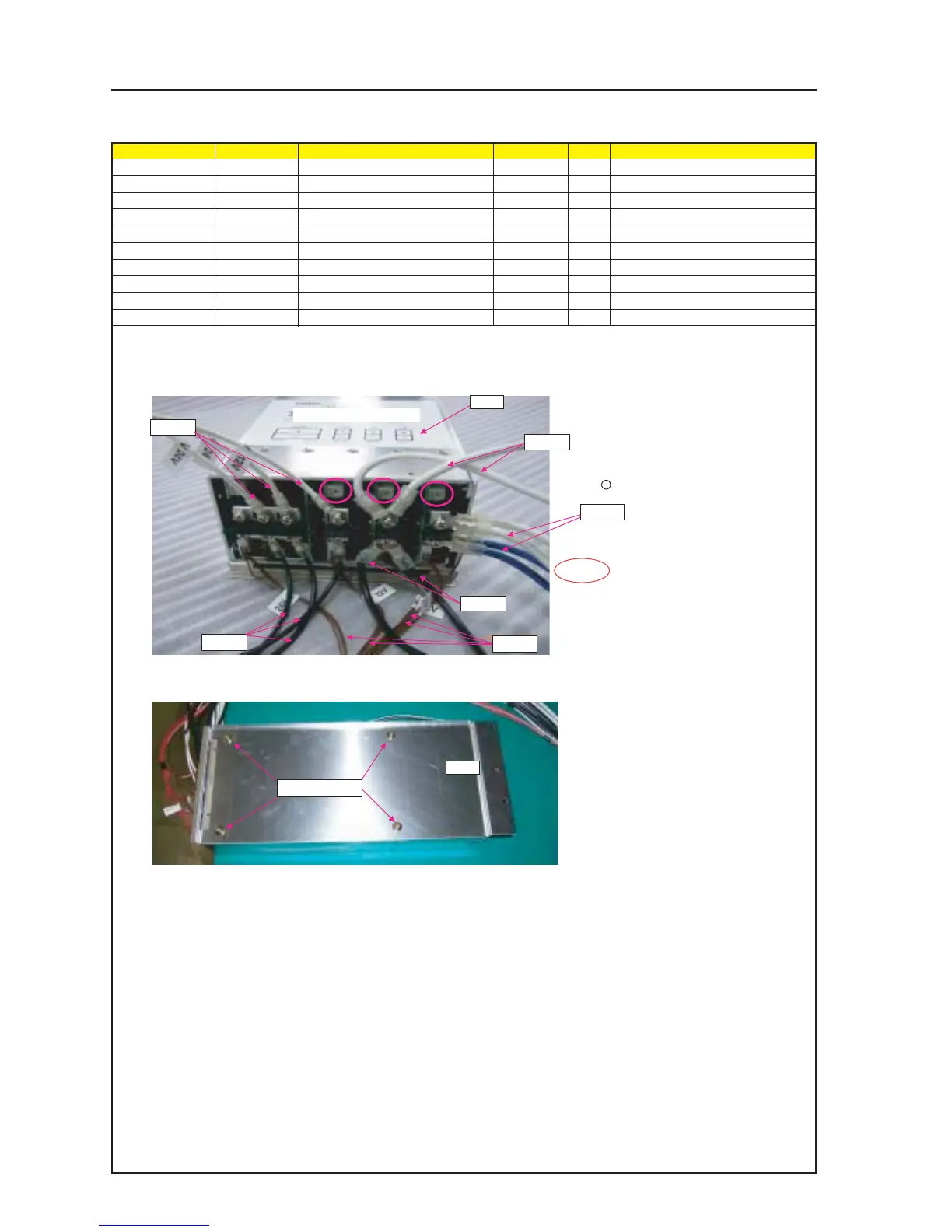
ASSEMBLY DIAGRAM
M-PS1
Diagram symbol Circuit symbol Part name Part code Q’ty Remarks
PRT1 POWER SUPPLY(AC6-2HECB-00) 3N101231 1
PRT2 BRACKET(M-PS) 24H55601 1
SRW141 PL-CPIMS*4*8*3GF 24V00591 4 Torque check
PSM1 CN4P(PSM1)700W,1015-12 7NW4N001 1
PSM2 CN6-WP(PSM2)700W,1015-12 7NW6N002 1
PSM3 CN6-WP(PSM3)700W,1015-18 7NW6N001 1
PSM4 CN14-WP(PSM4)700X,1061-28 7NWDV001 1
PRT2
SRW141 x4p
1 Remove the short-circuiting connector (this connector to be abandoned) that is inserted in the power unit.
Install the cable according to the instructions of the label that is stuck there.
* Fix it with a screw that is mounted on the power unit.
2 Do not block off the Volume(surrounded wih
circle ) over wire rod.
3 Attach M-PS on POWER SUPPLY UNIT.
Torque: 12~14kgf•cm
PSM3
PSM4
SAFETY
* Check current rating 50A.
*Check CABLE looseness.
PRT1
PSM1
PSM2
PSM2
PSM3
24V 12V 5V 3.5V