9-15
“Confidential, Do Not Duplicate without written authorization from NEC.”
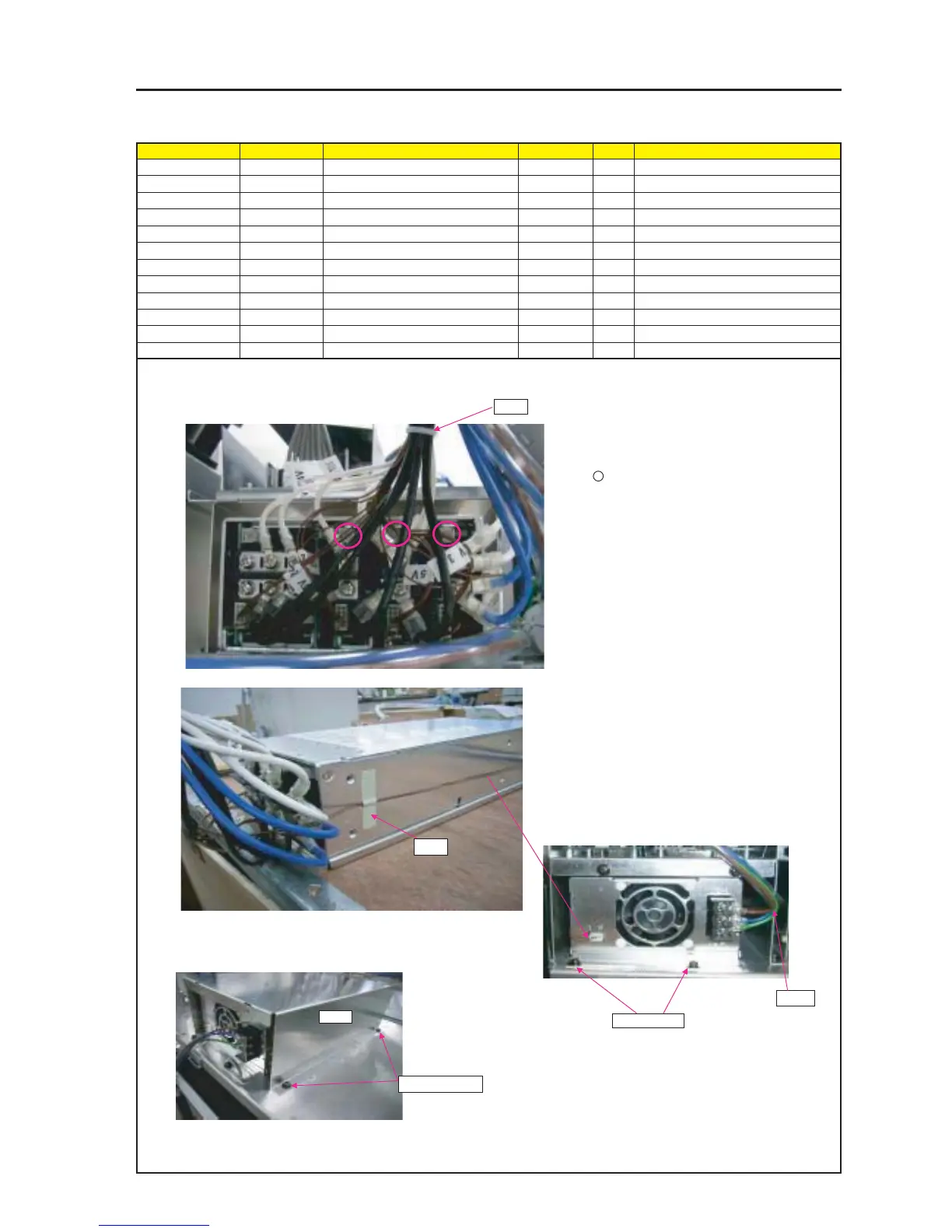
ASSEMBLY DIAGRAM
M-PS2
Diagram symbol Circuit symbol Part name Part code Q’ty Remarks
PRT1 BAND (L=100,T18R) 24C09121 1
PRT2 TAPE,SCOTCH NO.214 92203051 1
SRW019 PL-CPIMS*4*10*3KF 24V00461 2 Torque check
AC3 CN3-WP(AC3)280W,1015-18 7NN3V001 1
PRT3 BRACKET(BYPS) 24H60011 1
SRW035 PL-CPIMS*4*10*3KF 24V00461 4 Torque check
* Cut excess off.
CAUTION : When POWER SUPPLY (AC6-2HECB-0 set to the FLAME ASSY,
Do not hold the wiring Between Holding Bracket and Bracket(M-PS).
PRT1
PRT2
1 Bind the cables "PSM3" and "PSM4" with a wire harness band.
2 Lift up and bundle PSM4 wiring to not
droop down.
4 Uncover and screw tightly with the screw attached to
the POWER SUPPLY UNIT.
Torque : 12~14kgf•cm
After assembling, close the protective cover and lock
it.
3 Fasten the wiring material of PSM4 with a tape.
5 Put PSM4 wiring into thePOWER SUPPLY UNIT
connector.
6 Insert M-PS guide-hole to the BRACKET on the back
surface.
7 Put BYPS over POWER SUPPLY MAIN, and
attach to FLAME ASSY.
SRW019 X2P
CAUTION : Do not block off the Volume (surrounded with
circle ) over wire rod. It uses when the voltage adjusts
during adjustment process.
AC3
PRT3
SRW035 X4P
* Check CABLE looseness.