9-16
“Confidential, Do Not Duplicate without written authorization from NEC.”
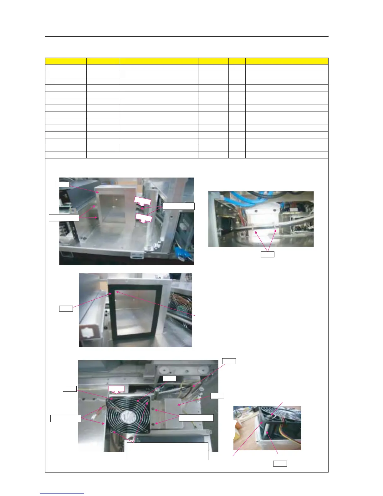
ASSEMBLY DIAGRAM
Diagram symbol Circuit symbol Part name Part code Q’ty Remarks
PRT1 DCFAN 4715KL 3N170098 1
PRT2 GUARD(FAN) 12265641 1
SRW109 PL-CPIMS*4*50*3KF 24V00531 2 Torque check
PRT3 DUCT(FAN)C 24H60901 1
SRW063 PL-CPIMS*4*10*3KF 24V00461 4 Torque check
PRT4 DUCT(FAN)ASSY 24HS4361 1
PRT5 CUSHION(T3) 24J34901 1
SRW082 PL-CPIMS*4*10*3KF 24V00461 4 Torque check
PRT6 CRAMP(RBWS-5N) 24C09281 5
PRT7 COLLAR (H28.2) 24H61481 2
PRT8 EDGE SADDLE 25283461 1
DCFAN
PRT1
PRT2
1 Attach DUCT(FAN) ASSY on FLAME ASSY.
2 Stick the cushion (T3) to the DUST (FAN) ASSY.
This cushion (T3) shall be stuck before the mounting
of the DUCT (FAN) ASSY.
3 After attaching DC FAN or GUARD (FAN) on DUCT
(FAN) C, attach it on DUCT (FAN) ASSY.
SRW109 X2P
Mounting screws are positioned in reverse
of those shown in the photo.
SRW063 X2P
PRT7
PRT4
PRT5
SRW063 X2P
SRW082 X2P
SRW082 X2P
* Paste it based on the
the corner.
PRT6
PRT6
PRT6
PRT3
COLOR(H28.2)
PL-CPIMS*4*50*3KF
DC FAN 4715KL
PRT6
PRT8