9-17
“Confidential, Do Not Duplicate without written authorization from NEC.”
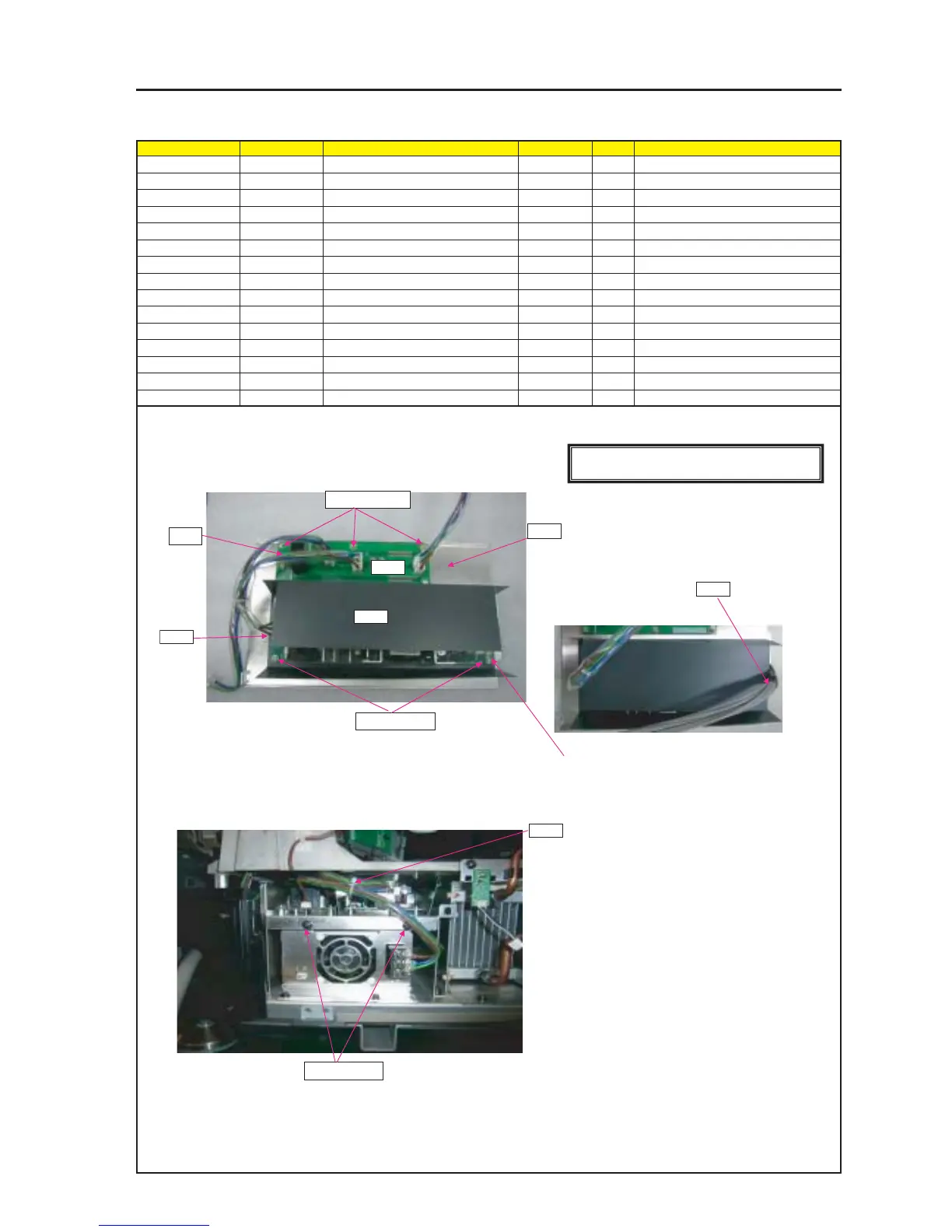
ASSEMBLY DIAGRAM
STANDBY
Diagram symbol Circuit symbol Part name Part code Q’ty Remarks
PRT1 ETC3_PWB PWB ASSY 81N94Z01
SRW113 SCREW,PL-CPIMS*3*8*3GF 24V00111 6 Torque check
PRT2 POWER SUPPLY(LEB100F-0524 3N100921 1
PRT3 BARRIER(PS) 24J34921 1
SCREW,PL-CPIMS*3*8*3GF 24V00111 4 Torque check
PRT4 BRACKET(ACPWB) 24H55581 1
SRW018 PL-CPIMS*4*10*3KF 24V00461 2 Torque check
AC2 CN5P(AC2)200W,1015-18 7NW5W050 1
PSS1 CN8P(PSS1)700W,1015-18 7NW8W030 1
PRT5 BAND (L=100,T18R) 24C09121 1
PRT1
1 Attach the AC-PWB ASSY to the mounting metal fitting (ACPWB).
To install the DC Power Supply, lay a barrier first and then install
it on the barrier. (Fit the DC power supply to the stud of the
mounting metal fitting first.)
2 Insert AC2 between AC-PWB and DC POWER
SUPPLY.
3 The BARRIER (PS) shall be mounted in a posture
where this side can be opened.
4 Bundle AC2 and AC with BAND.
5 Attach AC-PWB ASSY over BYPS.
SRW113 X6P
AC2
SRW114 X4P
PRT3
PRT4
PSS1
SRW018 X2P
[CAUTION] countermeasure against static electricity
Use WRISTSTRAP when handling of BOARD.
PRT2
PRT5
* The connector shall be inserted completely without permitting any rise.