9-19
“Confidential, Do Not Duplicate without written authorization from NEC.”
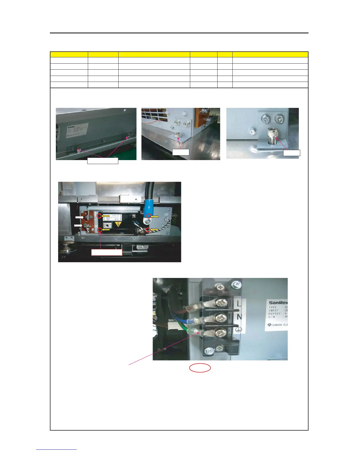
ASSEMBLY DIAGRAM
BALLAST PS2
Diagram symbol Circuit symbol Part name Part code Q’ty Remarks
SRW142 HHCS*8*20*3GF 24V00741 4 Torque check
SRW137 PL-CPIMS*4*16*3GF 24V00471 4 Torque check
1 Fix the BALLAST POWER SUPPLY with screws by entering it from the rear side of the
FLAME ASSY lower stage.
2 Attach IGNITER along the sides of POWER SUPPLY.
4 Remove TERMINAL BOARD COVER of POWER
SUPPLY BALLAST, attach CABLE(AC1) from
NOISE FILTERS.
Tightening torque : 50±5kgf•cm
5 Attach the removed TERMINAL COVER.
Tightening torque : 6±1kgf•cm
3 There is an accessory Bracket 4-6 mounted as described previously.
Connect this bracket to the terminal block of the ballast power supply
as illustrated at left.
* Fix the mounting metal fittings of the igniter and the terminal block
of the ballast power supply using accessory screws (M6).
Tightening torque: 55 ± 5kgf•cm
SRW142 X2P
SRW142
SRW142
SRW137 X4P
CAUTION : For GND cabling, use a spiral wire of green/yellow.
SAFETY
CABLE attachment should be used specified torque.