9-20
“Confidential, Do Not Duplicate without written authorization from NEC.”
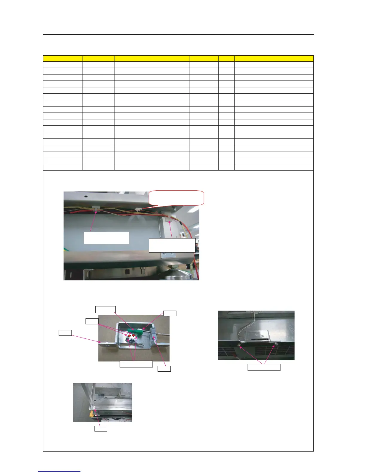
ASSEMBLY DIAGRAM
Diagram symbol Circuit symbol Part name Part code Q’ty Remarks
PRT1 CABLE CLIP(FCA-10) 24C02841 2
PRT2 BRACKET(COVER SW) 24H60331 1
PRT3 EDGE SADDLE 25283461 1
PWB1 ETC3 PWB PWB ASSY 81N94Z01 1
SRW144 CBIMS*2*8*3GF 24V01031 2 Torque check
SRW050 CFIMS*3*6*3KF 24V00421 2 Torque check
PRT4 CABLE CLIP(FCA-10) 24C02841 1
CN1 CN12-WPTE2)300X, 1685-28 7NWBV007 1 TSENS
CN2 CN5P(STA)1550W,1685-28 7NW5W067 1 LED
CN3 CN2P(COV)1600W,1061-26 7NW2W059 1 Rear SW
PRT5 GLUE,SCREW LOCK 92201082
BALLAST PS3
PRT1
Clamp CN2-3.
1 Attach CABLE CLIP(FCA-10) on FLAME ASSY, and also clamp CN1-3.
PRT1
Clamp CN1-3.
Let CN-1 upward into this
hole, connect up to Rear
SW.
PRT2
PRT3
2 Attach COVER SW PWB or EDGE SADDLE on BRACKET (COVER SW).
Insert COV CONNECTOR into COVER SW PWB.
PWB1
SRW144 X2P
SRW050 X2P
3 Attach COVER SW ASSY on FLAME.
COV
PRT4
4 Paste CABLE CLIP, infix CN1 CABLE.
PRT5