9-22
“Confidential, Do Not Duplicate without written authorization from NEC.”
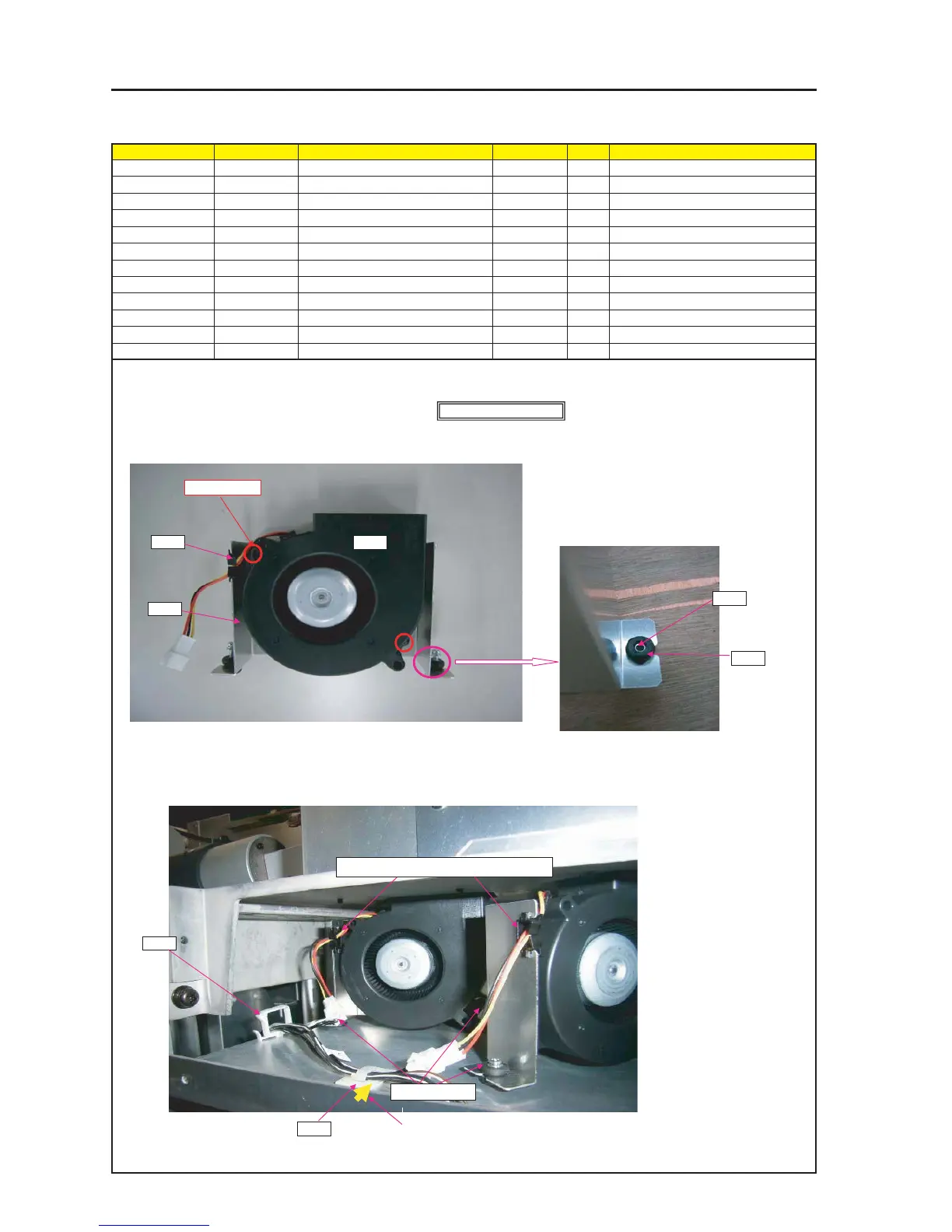
ASSEMBLY DIAGRAM
Diagram symbol Circuit symbol Part name Part code Q’ty Remarks
PRT1 DCFAN 9BAM24GD2-2 3N170100 2
PRT2 BRACKET(C FAN) 24H60871 2
SRW109 PL-CPIMS*3*15 24V00251 6 Torque check
SRW110 PL-CPIMS*4*10*3KF 24V00461 4 Torque check
PRT3 EDGE SADDLE 25281281 2
PRT4 CUSHION 24C09141 6
PRT5 COLLAR 24C09171 6
PRT6 CRAMP(RBWS-5N) 24C09281 1
PRT7 CABLE CLIP(FCA-10) 24C02841 1
C FAN
PRT1PRT3
1 Attach DC FAN on BRACKET(C FAN).
2 Attach EDGE SADDLE on BRACKET(C FAN).
4 After the DC fan has been installed, mount the mounting metal fittings (Fan C) on the frame.
3 Fit a cushion material to the fixing section of the
mounting metal fittings (Fan C), and pass a collar.
SRW110 X 2P
SRW060 X6P
PRT2
PRT4
PRT5
Assemble 2 sets.
* Insert FAN CABLE into EDGE SADDLE.
PRT7
PRT6
5 Stick the cable clip in a posture so that the cable can be fixed in this direction.
The position for adhesion shall be around the center of the straight line between
the GROMMET (G-50) and the CABLE CLIP (FCA-10).