9-23
“Confidential, Do Not Duplicate without written authorization from NEC.”
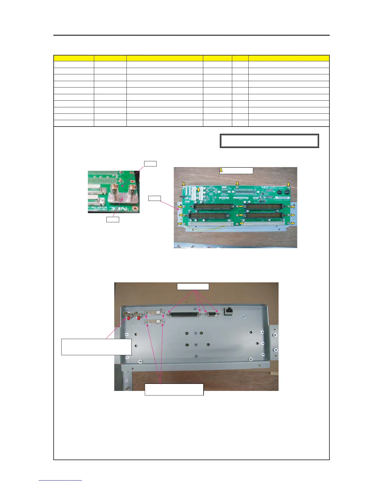
ASSEMBLY DIAGRAM
TI BOX1
Diagram symbol Circuit symbol Part name Part code Q’ty Remarks
PRT1 MOTHER PWB PWB ASSY 81N94M01 1
PRT2 PLATE(BNC) 24H46901 1
PRT3 SHIELD CASE A ASSY 24HS4381 1
SRW125 SCREW,PL-CPIMS*3*8*3GF 24V00111 13 Torque check
PRT4 STUD(D-SUB H5*.3) 24N08192 4 Torque check
GLUE,SCREW LOCK 92201082
PRT1
PRT2
1 Insert PLATE(BNC) on BNC after removing NUT and STUD on MOTHER_PWB.
Put MOTHER_PWB on SHIELD CASE A ASSY, and turn it back.
2 Screw the MOTHER_PWB.
3 Put MOTHER_PWB on SHIELD CASE A ASSY, turn it back.
Fix BNC CONNECTOR with hexagon nut and washer removed from BNC CONNECTOR.
PRT4 X4P
SRW125 X13P
PRT3
Fix the DVI-D connector after
removing the accessory stud.
*Tightening torque : 27±2kgf•cm
* After a hexagon nut has been fixed,
apply a screw lock agent.
[CAUTION] countermeasure against static electricity
Use WRISTSTAP when handling the BOARD.