9-24
“Confidential, Do Not Duplicate without written authorization from NEC.”
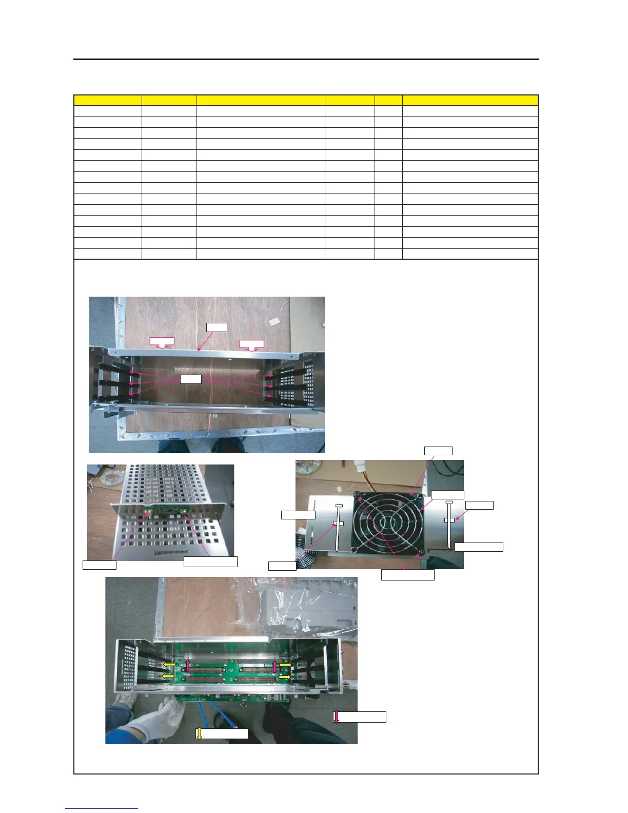
ASSEMBLY DIAGRAM
Diagram symbol Circuit symbol Part name Part code Q’ty Remarks
PRT1 GUIDE RAIL 24C02751 6 Amperage Rating 50A
PRT2 SHIELD CASE B ASSY 24HS4392 1
SRW085 PL-CPIMS*4*10*3KF 24V00461 4 Torque check
PRT3 DCFAN 9B0824G102 3N170123 1
PRT4 GUARD(FAN)(80) 24C08421 1
SRW107 PL-CPIMS*4*50*3KF 24V00531 2 Torque check
PWB1 ETC3 PWB PWB ASSY 81N94Z01
SRW127 PL-CPIMS*3*8*3GF 24V00111 1 Torque check
SRW149 PL-CPIMS*3*8*3GF 24V00111 2
PRT5 CRAMP(RBWS-5N) 24C09281 2
PRT6 STRAP(1K-57) 24C08381 2
TI BOX2
PRT1
PRT2
PRT4
SRW107 X2P
BOTTOM Side
TOP Side
PRT3
PWB1
SRW127 X1P
1 Install the GUIDE RAIL on the HIELD CASE B ASSY.
The Shield Case B Assy may be deformed easily at the time of X6P installation.
Therefore, this installation should be carried out after a cushion material has been fitted as a jig. (Remove this jig after installation.)
2 Attach DC FAN and GUARD(FAN) on SHIELD CASE B ASSY.
Mount the label [DC Fan Installed ⇒ faced to the Shield Case
B Assy side.
The lead-out port of the wiring material shall be positioned on the
prism side.
PRT5
PRT5
PRT6
PRT6
SRW149 X2P
SRW085 X4P