9-25
“Confidential, Do Not Duplicate without written authorization from NEC.”
ASSEMBLY DIAGRAM
TI BOX3
Diagram symbol Circuit symbol Part name Part code Q’ty Remarks
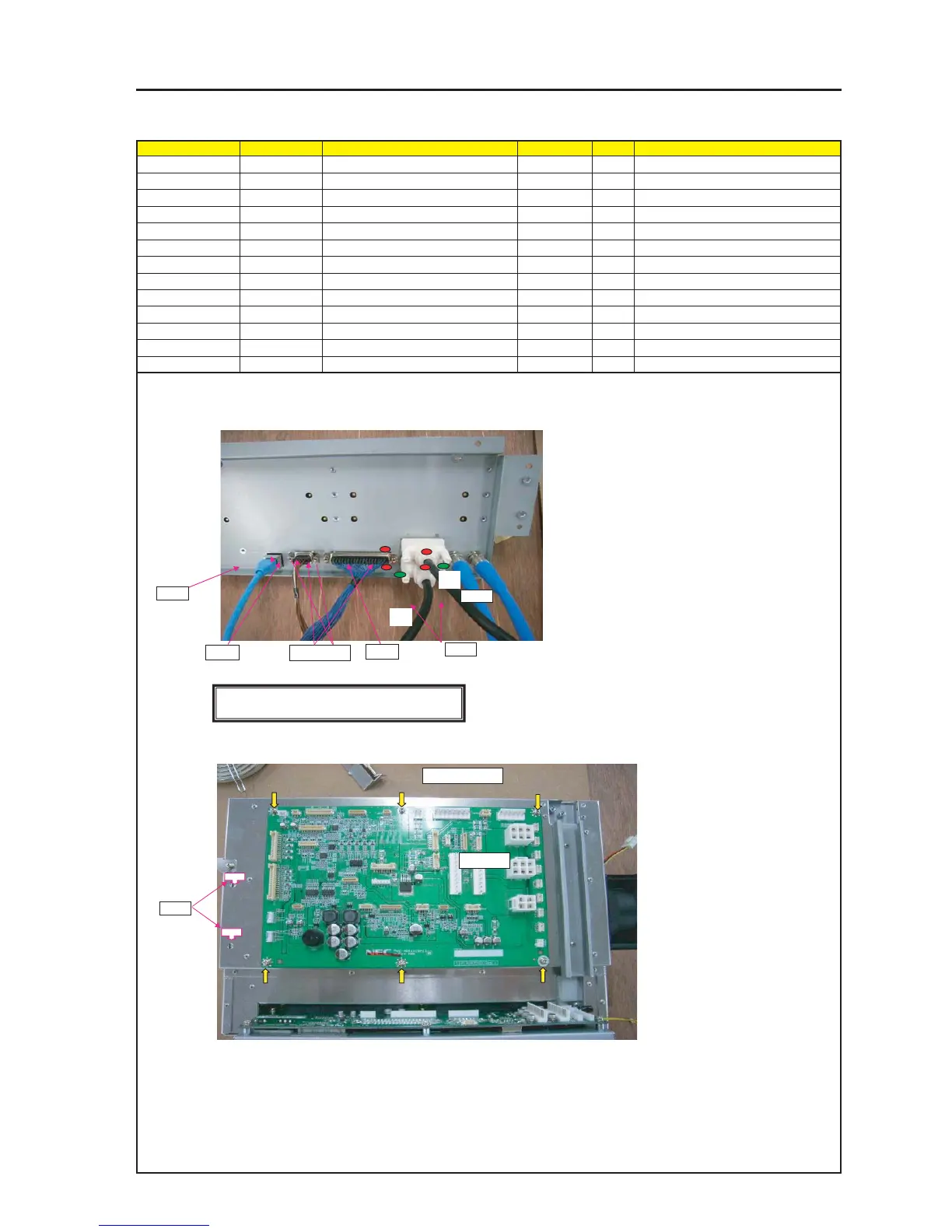
PRT1 STUD(D-SUB H*5.3) 24N08192 4 Torque check
PRT2 CABLE BNC D5FBC0042-SA 7N520062 2
PRT3 CABLE DVI-D SA0509049 7N520056 2
GP CN37-40P(GP)250W,1571-28 7NWLW046 1
CT CN9P(CT)250W,1061-26 7NW9W010 1
PRT4 CABLE LAN 0.33M PCRJE0033 7N520058 1
PWB1 PJDIV PWB PWB ASSY 81N94Y01 1
SRW126 SCREW,PL-CPIMS*3*8*3GF 24V00111 6 Torque check
PRT5 CRAMP(RBWS-5N) 24C09281 2
PRT2
PRT3
1 Fix D-sub37P(GP) and D-sub9P(CT) with STUD.
Attach each CABLE (BNC/DVI/LAN/GP/CT).
2 For the DVI-D cable, the inserted parts on lower side shall be given
a green marking on both sides (Terminal A side).
For the BNC cable, the inserted parts on left side shall be given a
green marking on both sides (Terminal A side).
For the DVI-D cable, a screw lock agent shall be applied after the
completion of screw tightening.
PRT X4P
SRW126 X6P
GP
CT
PRT4
PRT5
PWB1
[CAUTION] countermeasure against static electricity
Use WRISTSTRAP when handling the BOARD.
3 Attach PJDIV PWB ASSY.
USE SPACER JIG for not warpaging when screwing.
A
A