9-27
“Confidential, Do Not Duplicate without written authorization from NEC.”
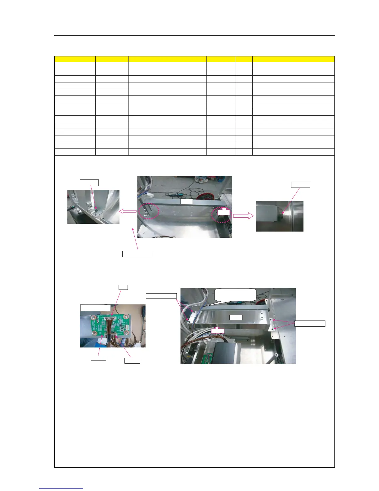
ASSEMBLY DIAGRAM
FIXING BRACKET TI
Diagram symbol Circuit symbol Part name Part code Q’ty Remarks
PRT1 BRACKET(PWB-U) 24H55551 1
SRW017 PL-CPIMS*3*10*3KF 24V00461 2 Torque check
PWB1 ETC3 PWB PWB ASSY 81N94Z01 1
SRW115 SCREW,PL-CPIMS*3*8*3GF 24V00111 4 Torque check
PRT2 FIXING BRACKET(TI UNIT) 24H60051 1
PRT3 CRAMP(RBWS-5N) 24C09281 2
SRW038 PL-CPIMS*4*10*3KF 24V00461 2 Torque check
SRW039 PL-CPIMS*6*14*3KF 24N02981 2 Torque check
CI CN8P(CI)300W,1061-24 7NW8W031 1
LPS CN12-18P(LP)1050W,1061-26 7NWXW004 1
PRT1
1 Attach FIXING BRACKET (PWB-U) on FLAME ASSY.
Attach FIXING BRACKET (PWB-U) on CLAMP.
2 Insert CONNECTOR CI and LPS into PEDE-A, connect CI on
CPU BOARD and LPS on LAMP POWER SUPPLY.
3 Attach FIXING BRACKET(TI UNIT) on FLAME ASSY.
Attach FIXING BRACKET(TI UNIT) on CLAMP.
SRW139 X4P
SRW017
SRW038 X2P
PRT3
PRT3
PRT2
SRW039 X2P
SRW115 X4P
PWB1
SRW017
CI
LPS
WIRE should be over
the BRACKET.