9-28
“Confidential, Do Not Duplicate without written authorization from NEC.”
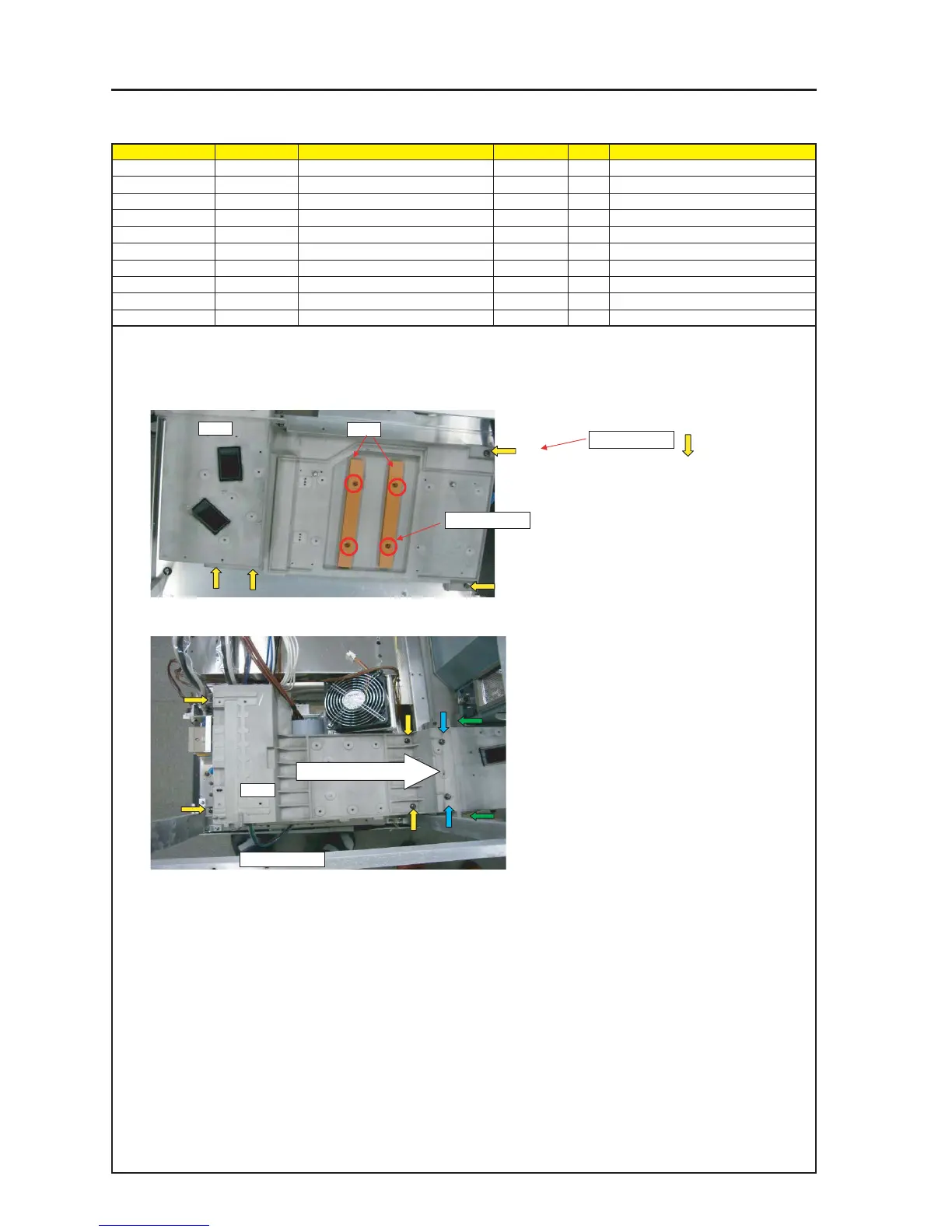
ASSEMBLY DIAGRAM
Diagram symbol Circuit symbol Part name Part code Q’ty Remarks
PRT1 LAMP BASE ASSY 24HS4331 1
SRW081 PL-CPIMS*6*14*3KF 24N02981 4 Torque check
PRT2 ENGINE BASE ASSY 24HS4251 1
SRW076 PL-CPIMS*6*20*3GF 24V01111 8 Torque check
PRT3 PLATE(LEF BASE) 24J34821 2
SRW086 PL-CPIMS*4*10*3KF 24V00461 4 Torque check
ENGINE BASE
1 Attach Lamp Base Assy on FLAME ASSY.
2 Attach Plate(Lef Base) on Lamp Base Asasy.
3 Attach ENGINE BASE ASSY on FLAME ASSY.
* When installing the engine base Assy, apply it to the lamp base side and tighten screws from above (blue arrow mark).
Then, tighten screws from the side (green arrow mark). Finally, tighten screws (yellow arrow mark) that are intended for
fixing the engine base Assy. In this case, the steps shall be made to a minimum between the engine base and the lamp base.
SRW076 X4P
PRT2
SRW081 X4P
PRT1
PRT3
SRW086 X4P
Apply it to the lamp base.