9-68
“Confidential, Do Not Duplicate without written authorization from NEC.”
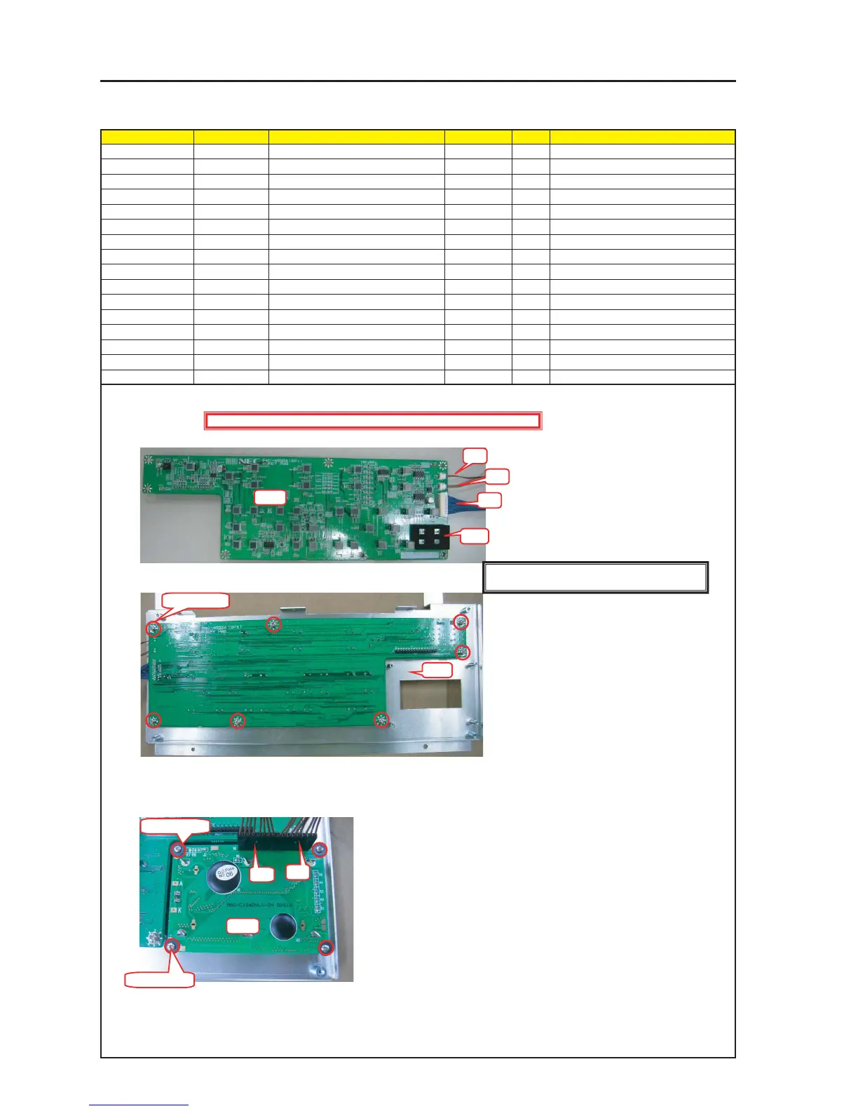
ASSEMBLY DIAGRAM
Diagram symbol Circuit symbol Part name Part code Q’ty Remarks
PWB1 PJKEY PWB ASSY 1
PRT1 SHIELD(LED) 24J28621 1
CN1 L1 CN2P(L1)100W,1061-26 7NW2W035 1
CN2 L2 CN2P(L2)380W,1061-26 7NW2W057 1
CN3 IF CN40P(IF)500W,1571-28 7NWLW047 1
PRT1 BRACKET(KEY) 24H60891 1
SRW123 SCREW,PL-CPIMS*3*8*3GF 24V00111 7 Torque check
PWB2 LCD_MODULE ASSY 81L23L01 1
SRW069 WASHER(D8-2.5) 24J28631 4
SRW129 CBIMS*2*6*3KF 24V00541 4 Torque check
CN4 LC CN8P(LC)600W,1061-24 7NW8W024 2
CTL1
1 Stick the Shield (LED) to the PJKEY PWB ASSY and insert CN-L1/CN-L2 and CN-IF in the same PWB.
2 Mount the PJKEY PWB ASSY on the Bracket (KEY).
3 Mount the LCD MODULE ASSY on the Bracket (KEY) and insert CN-LC in the LCD_MODULE ASSY
and the PJKEY PWB ASSY.
Caution: When mounting the LCD MODULE ASSY on the Bracket (KEY), make sure not to permit the intrusion of dust and contaminants.
Caution: The CN-LC shall not be inserted in a crossed posture.
CN1
CN3
CN2
PWB1
PRT1
PRT2
SRW123 X 7P
PWB2
CN4
CN4
SRW069 X 4P
SRW129 X 4P
Caution : External parts shall be handled carefully so that they are not damaged.
[Caution] Measures against static charges
Wrist straps shall be used while boards are handled.