9-69
“Confidential, Do Not Duplicate without written authorization from NEC.”
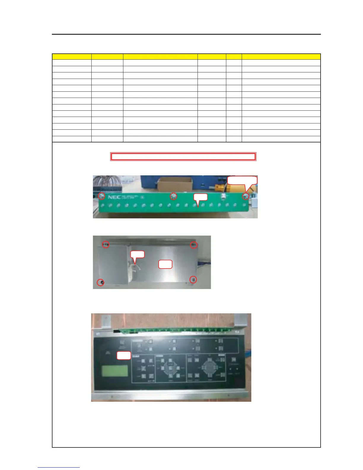
ASSEMBLY DIAGRAM
CTL2
Diagram symbol Circuit symbol Part name Part code Q’ty Remarks
PWB1 LIGHT-1 PWB ASSY 1
SRW120 SCREW,PL-CPIMS*3*8*3GF 24V00111 3 Torque check
PRT2 SHIELD PLATE(KEY) 24H60881 1
SRW061 SCREW,PL-CPIMS*3*8*3GF 24V00111 4 Torque check
PRT3 DECOR PLATE (KEY) 24K26401 1
PRT4 CRAMP(RBWS-5N) 24C09281 1
PRT5 BARRIER (LED) 24J35131 1
PRT6 ACETATE CLOTH TAPE 570F 9R030010 1
1 Install the LIGHT-1 PWB ASSY.
After the installation, insert the CN-L1 from the PJKEY PWB ASSY.
2 Stick the Décor Plate (KEY) to the Bracket (KEY).
3 Stick the Décor Plate (KEY) to the Bracket (KEY).
SRW120 X 3P
PRT1
PRT2
PRT3
Caution : External parts shall be handled carefully so that they are not damaged.
PRT4