9-71
“Confidential, Do Not Duplicate without written authorization from NEC.”
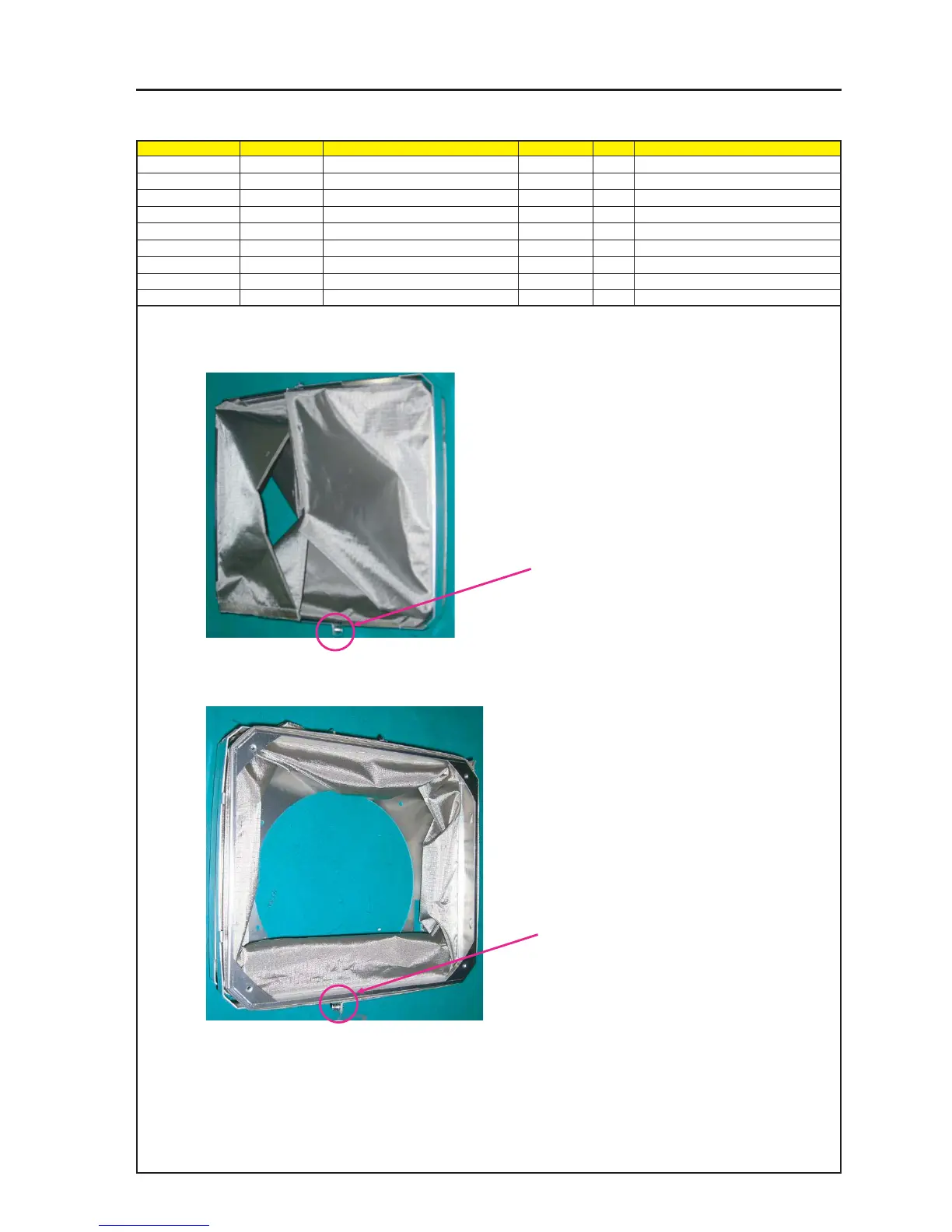
ASSEMBLY DIAGRAM
Lens food Sassy (2)
Diagram symbol Circuit symbol Part name Part code Q’ty Remarks
PRT1 SHIELD PLATE(NC1600C)B 24H60941 1
PRT2 SHIELDING SHEET(LENS) 24J24641 1
PRT3 HOLDER(SHIELD)A 24H56781 2
PRT4 HOLDER(SHIELD)B 24H56791 2
PRT5 SHIELD BOARD A 24H56751 1
SRW051 SCREW,PL-CPIMS*3*8*3GF 24V00111 2 Torque check
1 Hook the Shielding Sheet (Lens) on the Shield Plate (NC1600C) B.
2 In the state of 1 above, hook the Holder (Shield) A and the Holder (Shield) B, and fasten them with screws.
3 If there is any vacant Shielding Sheet (Lens) in the state of 2 above, hook it on the Shield Board A.
4 Similarly in the state of 2 above, hook the Holder (Shield) A and the Holder (Shield) B and fasten them with screws.
Caution : When fastening the Holder (Shield) A and the
Holder (Shield) B with screws, confirm that the
screws are not located on the Connector side
of the Lens Mount (PA67), but on the opposite
side (lower side).
(If they are located on the upper side, they will
come in contact with the Front Panel Sassy.)
Caution : When fastening the Holder (Shield) A and the
Holder (Shield) B with screws, confirm that the
screws are not located on the Connector side of
the Lens Mount (PA67), but on the opposite side
(lower side).
(If they are located on the upper side, they will
come in contact with the Front Panel Sassy.)