9-73
“Confidential, Do Not Duplicate without written authorization from NEC.”
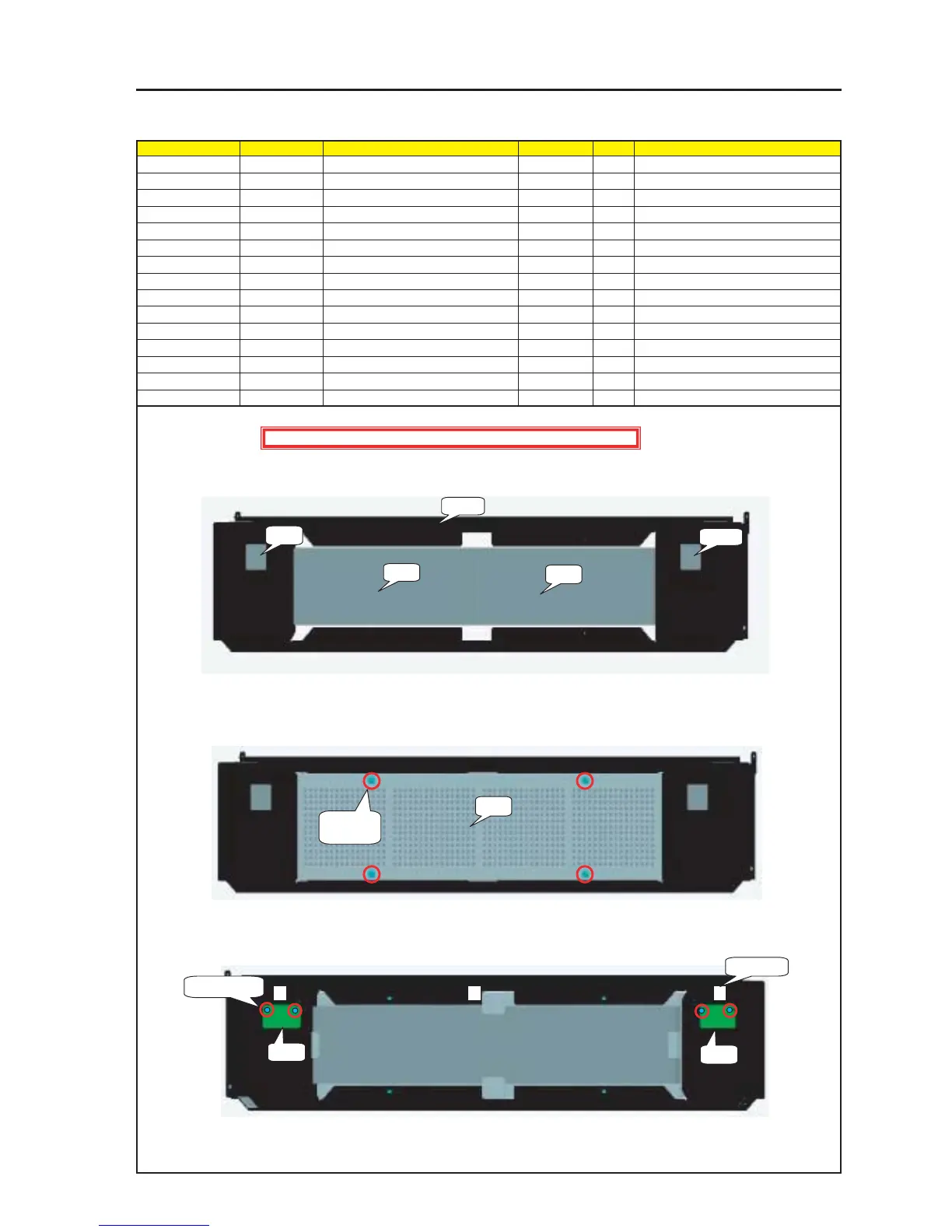
ASSEMBLY DIAGRAM
Rear Panel B Sassy
Diagram symbol Circuit symbol Part name Part code Q’ty Remarks
PRT1 REAR PANEL B ASSY 24PS5321 1
PRT2 DIFFUSER 24K26381 2
PRT3 CABLE CLIP(FCA-10) 24C02841 3
PWB1 SLED-A PWB ASSY 1
SRW124 SCREW,PL-CPIMS*3*8*3GF 2 Torque check
PRT4 FILTER B 24J28391 2
PRT5 FILTER CASE(REAR) 24P05491 1
PRT6 SPECIAL SCREW(M4*18) 24N08431 4 Torque check
PRT7 PIWA*4*3GF 24V00661 4
CN1 CN3P(ST1)625W,3265-24 7NW3W088
1 Mount the Diffuser on the Rear Panel B Assy.
2 Mount the Filter B on the Rear Panel B Assy.
3 Mount the PIWA*4*3GF and the Special Screw (M4*18) on the Filter Case (Rear).
(The rear Filter Cover Sassy is the Assy product of PRT4 as well as SRW*** and SRW***.)
4 Install the Rear Filter Cover Sassy on the Sassy of 2.
5 Reverse the Rear Panel B Assy and install the SLED-A PWB Assy and the ALED-B PWB Assy.
6 Stick the cable clip (FCA-10) to the Rear Panel B Assy.
7 Insert CN1 in the SLED-A PWB Assy and the ALED-B PWB Assy. Hang the wiring materials on the cable clip (FAC-10) of 6 for cabling.
PRT1
PRT4
PRT4
PRT5
PRT6 X 4
PRT7 X 4
PWB1
PWB2
SRW124 X 4
PRT3 X 3
PRT2
PRT2
Caution : External parts shall be handled carefully so that they are not damaged.